English
 Views: 0 Author: Elsa Long Publish Time: 2026-10-15 Origin: Site


Short answer: SMT stencil printing for fine pitch and 0201 components is not a print-accuracy problem that a better printer solves on its own. It is a total error budget problem. When the component shrinks from an 0402 chip to an 0201 chip, the paste deposit it needs shrinks from roughly a 0.5 × 0.6 mm pad to roughly a 0.3 × 0.35 mm pad, and the acceptable placement offset on a 0.4 mm pitch quad-flat-pack falls to the order of 50 µm. Nothing about the machine gets magically better, so every error source that was previously absorbed by the generous pad-to-pin clearance now has to be individually accounted for. Board-to-stencil alignment, vision-system resolution, stencil aperture geometry, squeegee force variation across the print stroke, board flatness under the print platform, paste powder size and paste rheology all contribute to the same final offset, and they add up. The selection question is therefore not "which printer is most accurate" but "which printer, stencil, support system and paste combination keeps the sum of every contribution inside the budget".
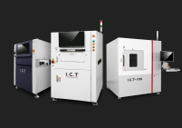
This guide is organised as a tolerance budget rather than a feature list, because that is how a fine-pitch print actually fails. Section 1 sets out the budget itself — how to arrive at the allowed total offset for a given component, and how to see which error sources scale with miniaturisation and which stay constant. Sections 2 to 6 then walk the six contributors in the order they act on the board: alignment and vision, the stencil, the squeegee, the board support, the solder paste, and the repeatability that the whole system holds over a production shift. Section 7 converts the budget into a machine-class match and a pre-purchase checklist, and Section 8 answers the questions buyers ask most often. To see the machine families this guide draws from, start at our I.C.T solder paste printer product hub, which lists the semi-automatic, fully automatic inline and long-board classes; this article assumes the component mix already demands fine-pitch capability and concentrates on what that demand requires of the equipment around the print.
Table of Contents
The stencil — aperture design and what the printer must support
Repeatability — what to measure and how to hold Cpk in production
Every SMT print that has ever been run had an error budget; most of them simply never had to be written down. When pads are wide relative to the placement tolerance and the pin pitch leaves visible clearance between a component lead and its neighbour, a printer can be off by 100 µm and the line still ships boards, because the process window is wider than the accumulated error. Fine pitch and 0201 remove that slack. A 0201 chip has a body length of about 0.6 mm and a width of about 0.3 mm; its paste deposit is only one or two hundred micrometres across. A 0.4 mm pitch QFP makes the situation even sharper, because the pad-to-pad gap is under 0.2 mm and the lead itself is thinner than the gap on each side. Once the acceptable offset is a fraction of a single paste deposit's width, every contributor to that offset has to be identified, measured and controlled, and a contributor that nobody thought to measure — a 20 µm sag under the print platform, or a vision system that resolves to 30 µm and not 10 µm — becomes the item that caps the whole line.
This section does three things. First it converts component miniaturisation into a concrete set of numbers, so that "fine pitch" stops being a marketing phrase and becomes a millimetre and micrometre specification. Second it builds a first-order tolerance budget: a table of the error sources that act on a print, with a realistic contribution for each, that can be filled in for a specific product before any machine is quoted. Third it separates the contributors into those that scale with miniaturisation and those that do not, because that split determines which investments actually buy accuracy and which merely move money around.
It helps to put real dimensions on the problem, because the gap between a comfortable print and a marginal one is not a couple of percent — it is an order of magnitude. An 0402 chip measures 1.0 × 0.5 mm and needs a paste deposit on a pad of roughly 0.5 × 0.6 mm, which is around 0.3 mm2 of aperture. An 0201 chip measures 0.6 × 0.3 mm and its pad is roughly 0.3 × 0.35 mm, around 0.1 mm2 — a footprint roughly one third the area, and a deposit volume that is smaller again once the stencil thickness is reduced from 0.12 mm to 0.10 mm or 0.08 mm to keep the area ratio acceptable. A 01005 chip goes further still, with a body near 0.4 × 0.2 mm and pad areas under 0.05 mm2, where the paste deposit is close to the resolution limit of a conventional 0.10 mm stencil and where Type 5 or Type 6 paste powder becomes mandatory rather than optional. On the leaded side, 0.5 mm pitch is routine, 0.4 mm pitch is the common fine-pitch case, and 0.3 mm pitch appears in high-density modules; at 0.4 mm pitch the gap between adjacent pads is about 0.2 mm, so a 100 µm lateral error already consumes half the clearance, and a 100 µm error is entirely normal on a printer that has not been set up for this class of work.
The demand this places on the print has three components, and it is worth stating them separately because they are often conflated. The first is volume repeatability: the deposit has to be the right size to form a fillet that will hold the component through reflow, and it has to be that size on every pad, every board, all shift. The second is positional repeatability: the deposit has to sit on the pad with enough margin that the placement machine's own offset plus reflow self-alignment can still recover. The third is shape fidelity: apertures for 0201 are close to square and small enough that a deposit which slumps, smears or bridges is a defect rather than a cosmetic variation. A printer can be excellent at the first and poor at the second, which is why a machine that prints beautiful large pads can still fail a fine-pitch product.
The budget is simply a list of the independent error sources that contribute to the final offset of a paste deposit relative to its pad, each with a number attached. The numbers below are first-order figures for a well-maintained inline printer running a 0.4 mm pitch product on a 0.10 mm stencil; they are meant to be replaced with the buyer's own measured values, but they show the shape of the problem and the relative weight of each term. Reading the table left to right, the first three rows are machine and setup contributions, rows four to six are consumable and tooling contributions, and rows seven to nine are the physical contributions of board, paste and environment. The useful property of a table like this is that it converts a vague complaint — "the print is inconsistent" — into a ranked list of things to check, and it shows immediately that no single row dominates, so no single upgrade fixes the problem.
# | Error source | Typical contribution | Scales with miniaturisation? | Where it is controlled |
|---|---|---|---|---|
1 | Board-to-stencil alignment (fiducial capture and table motion) | 15–30 µm | No — absolute, but becomes exposed | Vision system, fiducial design, table mechanics |
2 | Vision system resolution and fiducial contrast | 10–25 µm | No — absolute | Camera resolution, lighting, fiducial quality |
3 | Stencil-to-frame and frame-to-carriage registration | 10–20 µm | No — absolute | Frame clamping, stencil manufacture, repeatability of load |
4 | Aperture geometry error vs. design | 5–15 µm | Yes — becomes a larger fraction of the aperture | Stencil laser cutting, electropolishing, design shrink |
5 | Squeegee force variation across the stroke | 10–30 µm equivalent | Yes — small apertures release less forgivingly | Squeegee head levelling, blade condition, force control |
6 | Stencil tension loss over the frame span | 5–20 µm equivalent | Yes — sag becomes comparable to aperture size | Stencil tension specification and gauge checks |
7 | Board flatness and support-induced deflection | 20–60 µm | Yes — lands directly in the alignment term | Support density, vacuum or pin tooling, board thickness |
8 | Paste rheology drift (drying, temperature, shear history) | 10–40 µm equivalent | Yes — small apertures stop filling first | Paste type, open time, mixing, stencil wipe cadence |
9 | Thermal drift of machine and board during the shift | 5–20 µm | No — absolute | Warm-up, ambient control, calibration interval |
The way to use the budget is to total it and compare against the allowance for the product. If the acceptable total offset for a 0.4 mm pitch device is on the order of 75 µm — which is itself a function of pad width, lead width and the placement machine's contribution — then the table above already sums to a range that can exceed it, which is exactly the point: on a fine-pitch product, the printer, the stencil, the support and the paste are not separate purchases, they are one system that has to be budgeted together. The buyer who evaluates a printer by its advertised repeatability figure alone is looking at rows 1 and 2 and ignoring the other seven.
The split between scaling and fixed error sources decides where money is best spent. Fixed contributors — alignment mechanics, vision resolution, frame registration, thermal drift — are absolute numbers in micrometres; they do not grow when the component shrinks, but they become a larger and larger fraction of a shrinking allowance. That makes them the first place to look when a printer that was perfectly good on 0402 suddenly fails on 0201: the machine did not get worse, the allowance got smaller. Because they are fixed, they are also the contributors that are most efficiently reduced by machine specification, which is why vision resolution and table mechanics carry so much weight in fine-pitch printer selection.
Scaling contributors behave differently. Aperture geometry error, squeegee force variation, stencil sag and paste rheology drift all cause a roughly constant relative variation — the deposit is off by a percentage — so their absolute effect falls with aperture size at exactly the rate the allowance falls, meaning they do not automatically become harder to meet. What changes is the mechanism of failure. A paste that releases cleanly from a 0.6 mm aperture may not release at all from a 0.3 mm aperture, because the area ratio crosses the release threshold; a tension loss that is invisible on a standard frame becomes a visible deposit-height gradient on a fine-pitch one. In practice this split means the selection conversation should spend its time on the fixed contributors when choosing a machine, and on the scaling contributors when choosing a stencil and a paste — two different supplier conversations, both of which have to be settled before the printer is useful.

Alignment is where the fine-pitch print is won or lost, because it is the one step that can put a perfectly formed deposit in the wrong place by a distance large enough to matter. The printer's job at this stage is to establish where the board actually is, relative to where the stencil apertures actually are, and to move one to the other within a few tens of micrometres — and to do it again on the next board without drift. It sounds simple and it is not, because the measurement and the motion both carry error. The camera has a resolution limit, the fiducial it looks at has a manufacturing tolerance, the table that carries the board has backlash and thermal expansion, and the stencil sits in a frame that was clamped by hand. On a 0402 product all of these add up to a number that is comfortably smaller than the clearance available. On 0201 they do not.
This section covers the four things that determine whether alignment buys the buyer anything. It looks at fiducial design and count, because a vision system can only be as good as the marks it is given. It interprets what an alignment accuracy specification actually means, because catalogue numbers and production numbers are not the same quantity. It separates accuracy from repeatability, because on a production line the second is what determines yield. And it traces the alignment budget from the camera through to the print carriage, to show where micrometres are actually spent.
Fiducials are the reference marks the vision system measures to locate the board, and their quality sets a hard ceiling on achievable alignment. The standard guidance in IPC documentation and in most fabrication datasheets is a solid copper pad with a clear solder-mask opening and a defined contrast against its surroundings, typically 1.0 mm diameter with a mask clearance of at least 0.5 mm, positioned diagonally opposite each other on the panel. For fine-pitch work three details matter more than the size. First, contrast: a fiducial whose mask opening is under-sized, or whose copper is partially covered by mask or legend, gives a smeared edge and the vision system reports its centre with an uncertainty that goes straight into the budget. Second, count and placement: two global fiducials at the board corners locate the board as a rigid body, but they do not compensate for local stretch or for panel distortion between them, so a fine-pitch panel benefits from local fiducials near the fine-pitch devices as well. Third, flatness: a fiducial adjacent to a large copper area that has a different height, or a fiducial near a board edge that overhangs the support, will be measured at the wrong plane.
The practical failure mode is a product that aligns beautifully on the first board and drifts on later ones, which is almost always a fiducial problem rather than a printer problem. A fiducial that is only marginally visible will sometimes be captured and sometimes not, and because the machine needs a successful capture to align, a marginal fiducial produces intermittent alignment rather than random error — the worst pattern to debug because it looks like the machine is unreliable when the artwork is at fault. The remedy is to treat fiducials as a design deliverable with the same status as aperture geometry: specify diameter, mask clearance, contrast and count in the fabrication drawing, place local fiducials for fine-pitch devices, and verify the marks through the vision system before accepting the first article.
Printer datasheets quote alignment figures in a variety of ways, and the differences between them are large enough to change a purchase decision. A number such as ±25 µm may refer to the system's ability to bring a fiducial to a commanded position, to the residual error after alignment on a reference target, to a repeatability figure measured as a standard deviation over many cycles, or to a best-case figure measured on a glass plate rather than a real board. These are not comparable quantities. The first is a motion specification, the second is a closed-loop accuracy, the third is a distribution width, and the fourth is an idealised test. A buyer comparing two machines needs to know which quantity each figure represents and, preferably, to see the test conditions, because a ±50 µm repeatability measured on real boards is worth more than a ±25 µm accuracy measured on glass.
The other specification that deserves scrutiny is the camera field of view and its resolution. A vision system that locates a fiducial to within a fraction of a pixel on a large field of view is not necessarily more accurate than one with a smaller field of view and a higher magnification, because the limiting factor is the optical resolution of the mark's edge, not the pixel count. For fine-pitch work the useful questions are: what is the smallest fiducial the system can reliably capture, what magnification does it use for local fiducials, and how does it behave when the fiducial contrast is poor. If a supplier cannot answer those questions with numbers, the alignment figure on the datasheet should be treated as a motion specification only.
Quoted figure | What it actually measures | Useful for fine-pitch selection? | Question to ask the supplier |
|---|---|---|---|
Positioning accuracy (e.g. ±25 µm) | Motion system error at a commanded position, usually open-loop or on a reference target | Partly — it sets the mechanical floor | Measured on a real board or a glass plate? Over how many cycles? |
Alignment accuracy (e.g. ±10 µm) | Residual error after the vision loop closes on a fiducial | Yes — this is the number that enters the budget | Fiducial size and contrast used in the test? |
Repeatability (e.g. 3σ = 15 µm) | Spread of results over repeated cycles — a distribution width, not a limit | Yes — production yield is governed by the spread | Over what period, and with what thermal soak? |
Camera resolution (e.g. 5 µm/pixel) | Optical sampling of the fiducial edge | Only with the field of view stated | Smallest reliable fiducial, and local-fiducial magnification? |
For a production line the number that decides yield is not how accurate the machine is on its best cycle but how tightly it repeats across thousands of cycles. A machine with a 40 µm systematic offset that is stable board to board will pass a fine-pitch product comfortably if the offset is calibrated out; a machine with a 10 µm mean but a 35 µm spread will fail intermittently and be far harder to live with, because the offset cannot be compensated — it changes. This is why a mature fine-pitch line cares about the alignment distribution rather than its centre, and why commissioning a new printer involves running a statistically meaningful number of alignments and looking at the histogram, not checking one board.
The practical implication for selection is that repeatability has to be demonstrated under production conditions. A machine measured in an air-conditioned showroom, thermally soaked, on a fixture, will show a tighter spread than the same machine on a factory floor in the morning before it has warmed up. Since thermal drift is a fixed contributor in the budget, the useful test is a warm-up study: measure the alignment distribution from cold start through the first two hours of operation, and confirm that the centre does not walk outside the budget once the machine reaches steady state. A supplier who will run that test, or who publishes a drift figure, is offering something more valuable than a better nominal accuracy number.
It is worth tracing the alignment chain end to end, because a surprising amount of it is spent before the vision system is involved. The chain begins with the stencil: the apertures are placed relative to the stencil frame by the stencil maker, so the stencil's own manufacturing tolerance is already in the budget. It continues through the load: how the operator or loader places the frame in the carriage, and how repeatably the carriage clamps it, adds a term that varies every time the stencil is changed. Only then does the vision system measure the board, and only then does the machine move the table to close the gap. Finally, the print itself introduces a small additional offset because the squeegee drags the paste slightly as the blade passes, and the board can shift microscopically when the stencil separates.
Because the chain has this many links, the efficient approach to buying alignment performance is to specify the whole chain rather than one component. That means asking about stencil frame repeatability and clamping design in the same conversation as vision resolution, and asking how the machine verifies its own alignment — whether it re-measures fiducials after a stencil change, whether it tracks drift, and whether the operator can see the fiducial image and intervene. On a fine-pitch product these workflow features are not luxuries; they are the difference between an alignment system that holds the budget for a shift and one that requires a re-calibration every few hours. The same logic carries into general machine selection, which is why our SMT solder paste printer selection guide for production lines treats alignment and vision as a workflow specification rather than a single number.
The stencil is where the print's geometry is actually defined, and on a fine-pitch product it is a design deliverable rather than a consumable purchase. The reason is the area ratio: the relationship between the area of an aperture and the area of its internal walls. Paste transfers from the aperture to the pad because the adhesion between paste and pad overcomes the friction and adhesion holding the paste in the aperture, and as the aperture shrinks both effects scale, but not at the same rate. The walls shrink with the perimeter while the pad contact shrinks with the area, so a smaller aperture has proportionally more wall and less pad contact, and past a certain ratio the paste simply prefers to stay in the stencil. That threshold is a design fact, not a printer feature, which is why a stencil that works on 0603 will silently stop releasing on 0201 even when nothing else about the process has changed.
This section deals with the stencil from both sides: the design decisions that determine whether the paste will release at all, and the machine-side requirements that let a fine-pitch stencil do its job — framing, tension, clamping and protection. It starts with the area-ratio rule that sets stencil thickness, moves to the geometry choices that help small apertures release, covers the tension and framing requirements that keep the stencil flat over the print area, and closes with what the printer has to do to support and protect a thin, high-tension foil.
The area ratio is the aperture opening area divided by the area of the aperture's internal walls, and it is the single most useful number in stencil design. For a rectangular aperture of length L, width W and stencil thickness T, the ratio is (L × W) / (2 × T × (L + W)). The widely cited working guideline, set out in IPC-7525 and repeated by every stencil supplier, is that the area ratio should be at least 0.66 for reliable paste release, with 0.75 or better preferred for fine-pitch work; below roughly 0.5 the aperture becomes unreliable and the process needs rethinking rather than tweaking. The practical consequence is immediate: since T is in the denominator, the way to keep the ratio high while apertures shrink is to reduce the stencil thickness. A 0201 pad of about 0.30 × 0.35 mm has an area of 0.105 mm2 and a wall area of 2 × T × 0.65; at a stencil thickness of 0.12 mm the ratio is 0.67 — marginal; at 0.10 mm it is 0.81, and at 0.08 mm it is 1.01. That is why fine-pitch and 0201 work is run on 0.08–0.10 mm stencils rather than the 0.12–0.15 mm foil used for standard products.
Thinner foil, however, is not free. Reducing the thickness reduces the paste volume deposited on every pad, which on large pads may not be enough to form a fillet, and it reduces the stencil's stiffness and its resistance to sagging and damage. A product that mixes fine-pitch 0201 devices with large power pads therefore cannot always use a thin stencil everywhere, and the usual resolutions are a stepped stencil, where the foil is thinned only over the fine-pitch area, or a design that adds a second print pass for the coarse features. Both are legitimate, and both need to be decided with the stencil supplier rather than discovered at first article. The printer's role in this decision is only to be able to register and clamp the resulting stencil reliably, but the decision itself is what determines whether the product is printable at all.
Component | Approx. pad size | Pad area | Area ratio at T = 0.12 mm | Area ratio at T = 0.10 mm | Area ratio at T = 0.08 mm |
|---|---|---|---|---|---|
0603 chip | 0.60 × 0.80 mm | 0.48 mm2 | 1.43 | 1.71 | 2.14 |
0402 chip | 0.50 × 0.60 mm | 0.30 mm2 | 1.14 | 1.36 | 1.70 |
0201 chip | 0.30 × 0.35 mm | 0.105 mm2 | 0.67 | 0.81 | 1.01 |
01005 chip | 0.20 × 0.25 mm | 0.050 mm2 | 0.42 | 0.50 | 0.63 |
0.4 mm pitch QFP pad | 0.20 × 1.20 mm | 0.24 mm2 | 0.71 | 0.86 | 1.07 |
0.3 mm pitch pad | 0.15 × 1.00 mm | 0.15 mm2 | 0.54 | 0.65 | 0.81 |
The table shows why 01005 and 0.3 mm pitch work is a different class of project: even at 0.08 mm thickness the ratio is at or below the reliable threshold, which is the point at which the industry moves to ultra-thin foils, stepped stencils or specialised paste. It also shows that the same physical printer can serve both a 0603-heavy product and a 0201-heavy one, provided the stencil is designed per product — which is why the printer should be selected for its ability to handle thin, high-tension foils and fine apertures, not for a claim to print down to some component size on its own.
Once the area ratio is in range, geometry choices decide how much of the available release you actually get. Three adjustments are standard practice for fine-pitch apertures. The first is dimensional shrink: apertures are drawn slightly smaller than the copper pad, typically by 0.02–0.05 mm per side, which reduces bridging between closely spaced pads and compensates for the fact that a well-releasing paste often deposits slightly wider than the aperture. The second is corner rounding: square corners increase the local wall area and create a region where paste clings, so a small radius or a chamfer on the corners improves release and reduces the tendency for paste to remain in the aperture after separation. The third is wall finish: laser-cut apertures have a slightly tapered and roughened wall, and electropolishing or a controlled taper treatment reduces friction so the paste slides out rather than shearing.
A fourth choice applies to the aperture's trapezoidal profile. A stencil cut with a taper that is wider at the bottom than the top (the board side wider than the squeegee side) presents a slightly angled wall that the paste can slide along during separation, and this has the same purpose as electropolishing — reducing the work the paste has to do to leave. The practical limit is that a taper reduces the aperture's top opening, which lowers the paste volume and can make the deposit too small, so the choice is a trade against the volume the pad actually needs. For 0201 work the useful discipline is to have the stencil supplier state the taper, the shrink and the wall finish as part of the quotation, then confirm the resulting deposit with an SPI measurement on first article rather than trusting the design intent.

A stencil has to present a flat aperture plane to the board, and it does that by being stretched taut over a frame. Mesh tension is set when the stencil is made, and it decays with use, with temperature cycling and with printing. The specification that matters is a minimum tension measured with a tension gauge at the centre and at several points around the frame — commonly 35–50 N/cm for stainless foil on a well-framed stencil, with a minimum that the supplier should state. The frame itself matters: aluminium frames are light and inexpensive but deflect more under tension than steel or cast frames, and on a long or high-tension stencil the frame deflection shows up as a sag in the aperture plane at the centre, exactly where the fine-pitch devices usually sit. For fine-pitch work the practical guidance is a heavier frame section and a tension specification stated both as a target and as a rejection threshold.
From the printer's side, three things have to be right for a fine-pitch stencil to work. First, the frame has to be clamped repeatably, so that the stencil's position relative to the print carriage does not change when a stencil is changed; this is where a locating feature and a defined clamp sequence matter more than the clamp's force. Second, the stencil has to be supported so that squeegee pressure does not deflect it downward into the board — most fully automatic printers provide a stencil support ledge or air-bearing that lets the foil rest on the board's plane without being stretched further. Third, the machine has to protect the foil: thin, high-tension stencils are easily damaged by a mis-set squeegee, by a board that is not flat, or by a cleaning blade that presses too hard, and a printer without a stencil-protection interlock will convert a stencil cost into a throughput problem. These are specification items to confirm in the same conversation as aperture design, so the printer and stencil arrive matched.
Thin foil changes the mechanics of the print in ways a printer designed for 0.15 mm stencils may not handle gracefully. The most important is separation: after the squeegee passes, the board is lowered away from the stencil, and the rate at which it separates determines how cleanly the paste releases. On a thin stencil over a fine-pitch product, a slow, controlled separation — often a two-stage or programmable separation profile — gives the paste time to transfer rather than shearing. A printer that separates in a single fast motion will work on coarse products and produce torn or short deposits on fine-pitch ones. The specification to ask about is therefore a programmable separation profile, and whether the machine allows the separation speed to be set independently of the print speed.
Two further requirements follow from thin foil. First, stencil and board have to be parallel: the gap between the stencil's underside and the board's top surface has to be consistent across the print area, so the printer needs a demonstrated parallelism between the print platform and the stencil clamp. Second, the stencil has to be held without distortion during the print, which means the clamping and support arrangement must not pull the foil out of plane as the squeegee loads it. A useful acceptance test is to print a fine-pitch scale-adjustment pattern across the full printable area and measure deposit height at the centre and the corners: a printer whose stencil support and parallelism are correct will show a deposit-height variation of a few micrometres across the area, while one that is not will show a systematic gradient that no amount of squeegee tuning will remove.
The squeegee does two jobs that pull in opposite directions. It has to push paste across the stencil with enough pressure to fill every aperture completely, and it has to let the paste stay in the aperture rather than wiping it out or dragging it along the surface. On small apertures those two requirements tighten simultaneously: filling a 0.3 mm aperture demands enough pressure to overcome the paste's resistance to entering a small hole, while leaving the paste in place demands that the blade not scoop it back out on the trailing edge. The window between those two behaviours narrows as the aperture shrinks, and a printer that cannot control force, angle and speed independently will spend the product's maintenance budget chasing it.
This section covers the four squeegee variables that matter for fine pitch: the blade material choice, the force control that keeps the blade in contact without over-driving it, the speed at which the paste roll behaves predictably, and the blade alignment and wear that determine whether the first three hold across a shift.
Squeegee blades are made from metal, usually stainless steel or a specialty alloy, or from polyurethane in a range of hardnesses. Metal blades are rigid, they hold their edge, they wear slowly, and they are the usual choice for fine-pitch work because their sharp, hard edge produces a clean paste cut-off and holds a consistent printing angle under load. Polyurethane blades are softer, they conform to surface irregularities, and they are less likely to damage a stencil if a board is mis-loaded — but their edge deforms under pressure, and on small apertures that deformation means the blade cannot reliably wipe the surface clean, leaving paste outside the aperture. For 0201 work the standard recommendation is a metal blade, with a well-maintained edge and a controlled printing angle; polyurethane is chosen for coarse products or where stencil protection is the dominant concern.
The blade's own specifications matter as much as its material. Thickness affects how the blade deflects: a thin blade at a given force bends more, which changes the effective printing angle and the contact area, so blade thickness has to be matched to the force the machine applies. The edge condition matters more still: a blade with a nick, a rounded edge or paste dried on its trailing side will leave streaks and produce intermittent shorts, and on fine pitch those defects are far harder to see than on a coarse product because the apertures are too small to inspect by eye. A practical discipline is to inspect the blade edge under magnification at every stencil change and to replace on a schedule rather than on failure, because a worn blade degrades the print gradually and the resulting yield loss is easy to attribute to the product rather than the tooling.

Squeegee force is the single most commonly mis-set parameter on a stencil printer, and on fine-pitch products it has a narrow usable window. Too little force and the blade does not wipe the stencil clean — paste is left on the surface, filling the gaps between apertures and causing bridging. Too much force and the blade presses the stencil down onto the board, bowing it into the apertures, reducing the deposit volume and, on a thin stencil, permanently stretching or damaging the foil. The correct force is the minimum that keeps the blade in full contact with the stencil across its length, which is a function of blade length, blade thickness, printing speed and paste viscosity — and critically, it varies along the blade if the blade is not parallel to the stencil.
Parallelism is the mechanism behind most "squeegee force" problems on fine pitch. If the blade is higher at one end than the other, then setting the average force correctly leaves one end over-forced and the other under-forced; the print then shows a gradient — shorts or unfilled apertures at one side of the board and surface paste at the other — that changes when the board is turned round. Because the symptom mimics paste problems and stencil problems, the diagnostic that saves the most time is to print the same pattern with the board rotated 180°: if the defect moves with the board, the problem is in the board or stencil; if it stays with the machine, the problem is the squeegee head. Machines that offer automatic or assisted blade levelling, or a force readout per side, remove this diagnostic burden and are worth prioritising for fine-pitch production.
Print speed controls the shear rate the paste experiences as it passes under the blade, and paste is a shear-thinning material: it flows more readily when sheared quickly and reverts to a higher viscosity when the shear stops. That behaviour is what makes printing possible at all — the paste rolls and fills apertures under the blade, then thickens and stays put when the blade has passed. Because the effect is non-linear, there is a usable speed window for each paste, and the window shifts with aperture size. Speeds that are too low tend to leave the paste behaving more like a viscous liquid, causing it to slump or to be sucked out of small apertures; speeds that are too high can leave the paste insufficiently fluidised to fill a fine aperture completely, producing incomplete deposits at the leading edge of the print.
For fine-pitch work a typical starting window is a reasonably brisk print speed with a slightly slower separation, but the exact figures are paste-specific and should come from the paste supplier's data rather than from general advice. What belongs in the machine specification is the ability to set print speed and separation speed independently, and to reproduce them reliably from a stored recipe; and, because the print cycle is only part of the line's throughput, it is worth understanding how the print parameters interact with overall line rate before optimising them for print quality alone — the relationship between print parameters and line throughput is worked through in our guide on how to estimate solder paste printer cycle time and throughput, which is useful when a quality-improving change to speed has to be traded against cycle time.
The squeegee is a wearing part, and the properties that make a blade good for fine pitch — a sharp, straight, unworn edge and a repeatable printing angle — degrade with use in ways that a coarse product will not notice. A blade that has worn by a few tens of micrometres over its length, or that has accumulated hardened paste on its trailing face, will still print 0603 products acceptably while producing intermittent paste residue and shorts on a 0201 product. The rate of wear depends on the blade material, the stencil surface, the force used and the number of cycles, and on a fine-pitch line the practical answer is to measure rather than to estimate: keep a record of cycles per blade and of the deposit quality at each inspection, and replace on the basis of that record.
Blade alignment deserves the same treatment. A blade should be checked for parallelism against the stencil plane at each stencil change, using the machine's levelling feature if it has one, and the check should be recorded so that a drift over time becomes visible. Two further items belong in the shift-level routine. First, the paste roll should be watched for continuity — a roll that breaks or thins indicates a force or speed problem before it shows up as a defect. Second, the machine's own cleaning cycle has to be verified, because a cleaning blade or vacuum head that is not removing paste from the stencil's underside will contaminate the next print, and on fine pitch that contamination produces a characteristic scattered defect pattern that looks random until it is traced to the cleaning interval. These are the routines that hold the squeegee's contribution to the tolerance budget across a production shift rather than for the first hour of it.
Board support is the contributor that most often sits in the alignment budget without anyone naming it, and on fine-pitch products it deserves to be treated as a print accuracy specification rather than as a workshop convenience. The reason is straightforward. The alignment budget measures the offset between the board's fiducial centre and the stencil's fiducial centre as the machine sees them, but the board is not a rigid plate — it bows under its own weight, bows further under the squeegee load, and bows differently depending on where it is supported. A 0.4 mm pitch QFP pad that is nominally 20 µm from its fiducial will actually be 40 µm from it after the support deflects, which is exactly the kind of offset that turns a passing print into a failing one. The board is not lying to the vision system; the vision system is reporting the fiducial's position correctly, and the print is happening somewhere else on the board.
This section covers the four decisions that decide whether board support contributes to the budget or to the headline. It traces why flatness matters even when the board arrives flat, the support density required for thin boards, the choice between vacuum, pin and hybrid support, and the trade-off between board thickness, warpage and tooling cost. The same logic that constrains a fine-pitch product also constrains a long board, and the two together are the reason our guide on how to choose a solder paste printing machine for large and long PCBs devotes as much space to the support system as to the printable area — for both classes of product, the support is part of the print.
The bridge between flatness and alignment is straightforward to draw. The vision system measures fiducials at whatever plane they sit in. If the board is bowed upward at the centre and supported only at the edges, the fiducials — which are usually at the board corners — sit at one elevation and the centre of the board sits at another. The vision system therefore measures the board as a rigid body, but the centre of the board is displaced relative to the corners when the print platform pushes the board up to the stencil plane. The amount of that displacement is the support contribution to the alignment budget, and it can easily exceed 50 µm on a 0.5 mm board supported only by its edges under squeegee load.
Two practical details make the problem worse than the simple picture suggests. First, the board's flatness changes during a shift as it absorbs moisture and bakes in the reflow oven downstream; a board that is flat in the morning is bowed by the afternoon, and a support setting that was correct on the first board is wrong on the hundredth. Second, fine-pitch devices are usually placed at the centre of a board, which is exactly where unsupported boards bow most. The consequence is that the support system has to be evaluated on a worst-case board, not a best-case one, and the support density has to be specified for the thinnest board in the product mix, not the average.
The number that translates flatness into machine specification is the maximum allowed gap under the board, which in turn sets the spacing between support points. A common rule of thumb is that the gap should be small enough that the board's deflection under its own weight and under the squeegee load is below the alignment budget — say 25 µm or less. On a 1.6 mm FR-4 board with edge support that is easily achieved. On a 0.8 mm board it requires additional pins or a vacuum bed, and on a 0.5 mm board it requires a tightly spaced support grid. The rule is not theoretical: the deflection of a plate under a distributed load rises with the fourth power of the support span, so doubling the gap between supports increases the deflection by sixteen times, which is why the difference between a sparsely and a closely supported board is so much larger than it looks.
From the printer's side this translates to three options. A dedicated fixture machined for one board outline is the most repeatable solution and the most expensive, because every product change requires a new fixture. A pin nest with magnetic supports in a programmable grid is more flexible — the operator sets the support positions to match the board and changes the layout in a few minutes when the product changes. A vacuum bed is the most flexible of all, supporting any board outline without setup, but it supports by area rather than by point and is most useful on relatively flat boards rather than badly bowed ones. The choice between them is part of the printer specification and should be made on the same spreadsheet as the alignment figure, because a printer with a tight alignment number on a poorly supported board will underperform a printer with a looser alignment number on a well-supported one.
Vacuum support is the easiest to live with day to day. The board sits on a porous bed and air is drawn through, holding the board against the bed with a uniform pressure that flattens gentle bows. The advantage is that the support automatically matches the board outline, and there is no setup between products. The limit is that vacuum flattens by pressure, and a heavily bowed board or a thick board with a stiff bow will not flatten completely because the available pressure is bounded by what will not damage components already on a populated board — and a printer does not have to populate a board to face this limit, because the next process step usually does. Vacuum also supports the board across its whole underside, which means that a board with a mix of populated and bare areas sees a different support stiffness in each region.
Pin support, magnetic or mechanical, defines a finite set of contact points at operator-programmed positions. The advantage is that a pin pushes the board up at a precise location, so the support density can be matched to the board stiffness, and points of known high curvature can be lifted specifically. The limit is the setup time and the risk that a mis-set pin will lift the board off the print plane at a fine-pitch device. Hybrid support — a vacuum bed with magnetic pins that can be added or removed — combines both: the vacuum holds the board flat, and a small number of pins define the datum at the fiducial locations and the centre of the print area. On fine-pitch production the hybrid arrangement is the most common because it removes the setup-versus-rigidity trade that the other two alone impose. A useful acceptance test for any support arrangement is to print a 0201 or fine-pitch pattern with the board placed in three orientations — straight, rotated 90° and rotated 180° — and compare SPI measurements; a well-set support shows a consistent pattern, a poorly set one shows a systematic shift with rotation.
Support type | Setup time | Flexibility | Best at | Limit | Fine-pitch suitability |
|---|---|---|---|---|---|
Dedicated fixture | None in production; long per product | Low | Single-product high-volume lines | Cost and lead time per product | Excellent where justified |
Programmable pin nest | A few minutes per product | High | Multi-product fine-pitch lines | Operator error at changeover | Excellent when well-managed |
Vacuum bed | None | Very high | Relatively flat boards and short changeovers | Heavy bows, populated boards | Good for moderate flatness |
Hybrid (vacuum + pins) | A few minutes per product | Very high | Fine-pitch and mixed-format lines | Complexity of the support tooling | The most common fine-pitch answer |
Thickness and warpage together decide how aggressively the support has to work, and the design trades this presents are the same on a fine-pitch product as on a long board. A thick board resists deflection, but it does not fit every product, and a thin board flattens easily but is more sensitive to support point spacing. A 0.4 mm pitch QFP on a 1.6 mm board with 1% warp measured across the diagonal is at one end of the spectrum — easy to support, easy to print; the same QFP on a 0.6 mm board with 2% warp is at the other, and the printer's support system is the only way the print holds the budget. The practical lesson is that the support specification should be written against the thinnest, most-warped board the line will run, because that board is the one that will surprise the production team on a Friday afternoon.
The tooling trade comes in two further forms. A dedicated fixture for a thin, bowed board produces the most repeatable prints and the highest tooling cost; a magnetic pin nest produces slightly less repeatable prints and a much lower per-product cost; a vacuum bed is the lowest cost and the least repeatable. On a line that runs five to twenty products, the pin nest usually wins on total cost of ownership because the savings in time and tooling between products outweigh the small loss in repeatability. On a line that runs one product, the dedicated fixture is a better investment. And on a line that runs a mix of fine-pitch and standard products, the most flexible answer is a hybrid support that combines a vacuum bed with a programmable pin nest, with the pins used to define the datum and lift the centre of the print area while the vacuum does the general flattening. The same logic is part of the long-board and large-panel case, where the support is the dominant cost driver, and it is the reason a printer selection should not be made without looking at the support arrangement as a coherent feature set rather than as an optional extra.
Solder paste is a finely tuned mixture of metal powder, flux, rheology modifiers and a few percent of solvent, and on a fine-pitch product the powder and the rheology dominate everything else. The metal content and the alloy are the same as on a coarse product — the same SAC305 or similar — but the powder particle size, the viscosity and the thixotropy, the behaviour under shear, have to be chosen for small apertures. A paste that prints 0603 pads beautifully can fail to release from a 0201 aperture even when every other parameter is identical, because the largest particles in the powder are too big to pass through the small aperture, or because the paste's response to shear does not produce enough flow to fill the small hole at the print speed used. The paste is therefore a printed material as well as a solder, and the printer's interaction with it is part of the print's accuracy.
This section works through four aspects of the paste that the printer cannot fix. It describes the powder-size ladder and what each step buys. It explains the rheological properties that govern how the paste moves under the squeegee and releases from the aperture. It covers paste handling — temperature, mixing, stencil life — that determines whether the paste the machine sees at hour six of the shift is the same as the paste it saw at hour one. And it sets out the paste–printer interface, the parameters that have to be matched rather than chosen independently, including the HMLV-specific case of paste ageing in stencil life across a product mix, which is treated in our guide on selecting an SMT stencil printer for high-mix low-volume production.
Solder paste powder is graded by the diameter of the largest few percent of particles, expressed as the J-STD-005 type. Type 3 contains particles up to about 45 µm and is the standard paste for most surface-mount products. Type 4, with particles up to about 38 µm, is the workhorse for 0402 and standard fine pitch. Type 5, with particles up to about 25 µm, is the practical minimum for 0201 work, and is often used for 0.4 mm pitch. Type 6, with particles up to about 15 µm, is the limit of standard powder technology and is used for 01005 and 0.3 mm pitch work. Each step finer in the powder gives a smaller minimum aperture that the paste can pass, but it also makes the paste more expensive, more sensitive to shear history, more prone to drying on the stencil, and more demanding of storage and handling.
The choice is not automatic. Type 5 paste is roughly 30–50% more expensive than Type 4 and is harder to work with, and the right answer is to step down the powder only as far as the smallest aperture in the product mix requires. A product that has both 0603 and 0201 devices can often be run on Type 4 paste by using a stencil with a stepped thickness that thins the foil only over the fine-pitch area; a product that is exclusively 0201 or finer usually requires Type 5 or finer because the larger particles in Type 4 will block the small apertures and produce intermittent voids. The same logic applies to alloy choice — a no-clean paste with a more active flux will print more cleanly through small apertures but will leave more residue, so the choice is again a product decision, not a printer decision.
Powder type | Largest particles | Typical pitch range | Stencil thickness | Relative cost | Handling sensitivity |
|---|---|---|---|---|---|
Type 3 | ~45 µm | 0.65 mm and above | 0.12–0.15 mm | Baseline | Low |
Type 4 | ~38 µm | 0.4–0.65 mm | 0.10–0.12 mm | +10–20% | Moderate |
Type 5 | ~25 µm | 0.3–0.4 mm | 0.08–0.10 mm | +30–50% | High |
Type 6 | ~15 µm | 0.3 mm and below | 0.06–0.08 mm | +60–100% | Very high |
A paste's rheology is the set of properties that govern how it flows under stress. The most useful for printing are viscosity — resistance to flow under steady shear — and thixotropy — the property of becoming less viscous under shear and recovering when the shear stops. Thixotropy is what makes printing possible: under the squeegee the paste is sheared and flows; once the blade has passed, it thickens and stays in the aperture. The recovery has to be fast enough that the paste does not slump on the stencil before the board separates, and slow enough that the paste has time to level after the aperture is filled. The thixotropy is set by the flux chemistry and the powder surface treatment, and a paste that is too thixotropic will leave voids and incomplete fills because the paste does not flow into the aperture before the blade moves on; a paste that is too Newtonian will slump and bridge after the print.
The printer interacts with rheology in two ways. The first is print speed, which controls the shear rate the paste sees. Higher print speeds increase the shear, which can help fill small apertures but can also drag the paste along the surface if the speed is too high. The second is the print-stroke geometry — the length of the blade and the angle it presents — which determines the pressure distribution under the blade. On fine-pitch work the practical discipline is to start from the paste supplier's recommended speed and pressure and to vary one parameter at a time, because the rheology is what couples the two, and changing both at once produces an unintelligible result. A useful diagnostic is to print a small board at three speeds and measure the SPI deposit height at the same fiducial location: a paste that is well-matched to the speed window shows a flat curve, a poorly matched one shows a steep change with speed that is hard to control in production.
Fine-pitch paste is more sensitive to its environment than coarser pastes, and the printer's environment and handling routines have to be set up to accommodate it. Three handling details matter most. First, temperature: paste should be brought to the printer temperature — typically 20–25°C and not less — before the jar is opened and the paste is applied, because cold paste has higher viscosity and poor release from the stencil, and warming a jar on a hot plate or near a heater introduces gradients that produce inconsistent prints. Second, mixing: paste that has been sitting in the jar separates over time, and the metal content at the top of the jar is lower than at the bottom, so a thorough mix is needed before application. The mixing should follow the paste supplier's instructions, because over-mixing raises the temperature and changes the rheology.
Third, stencil life. Once a paste is on the stencil, it is exposed to air and its solvents evaporate slowly, the rheology drifts, and its ability to release from the aperture degrades. The supplier's stencil life — usually a few hours on the stencil — is the specification to work to, and the practical implication is that on a fine-pitch line the cleaning and re-paste cycle has to be set to that interval regardless of how much paste is left in the dispenser. A paste that is past its stencil life shows up as a slow drift in deposit volume over a shift, visible in SPI trends before it is visible to the eye, and the right response is a scheduled clean rather than a recipe change. The printer should be able to set cleaning intervals and paste replenishment volume as part of the recipe, and an SPI that shows drift over the shift is a signal that the handling routine is not keeping up with the paste specification.
Because paste, stencil, support, alignment and squeegee are coupled, the right way to commission a fine-pitch product is to set up the paste parameters, the stencil, the support and the squeegee together, and to vary one at a time. The order matters. The first decision is the stencil — its thickness, aperture design and tension — because it sets the geometric terms of the print. The second is the support — its density and arrangement — because it sets the offset contribution to the alignment budget. The third is the squeegee — its material, force and speed — because it sets how the paste enters and leaves the aperture. The paste is set last, because it is the most expensive to change once a jar is open, and the same paste will behave differently under different squeegee and speed settings.
The recipe that the printer stores has to capture all four sets of parameters, and the operator has to be able to see and edit them. A useful acceptance test is to run a fine-pitch scale-adjustment pattern with the recipe and to vary each parameter by a small amount, observing the SPI response: the parameter with the steepest SPI response is the one that the production routine has to keep closest to its set point, and the parameter with the shallowest response is the one the operator can adjust freely. The same logic applies to recipe management across a product mix, where the difference between products is the recipe, not the printer. A multi-product fine-pitch line is essentially a problem of managing a set of recipes, each of which is a complete statement of how the printer, the stencil, the support and the paste have been coupled, and the printer's role is to make those recipes reproducible at a level that the human operator cannot match unaided.
The earlier sections set up the print and keep it inside the budget on a single board. Repeatability is the question of whether the budget still holds on the ten-thousandth board of the shift, and it is the property that separates a printer that is spec-compliant from one that is production-usable. Repeatability is not a machine specification in the same sense as alignment accuracy — it is an outcome of the machine, the stencil, the support, the paste and the routine all behaving consistently together, and it is measured rather than quoted. On a fine-pitch product the measurement is the whole point: the deposits are too small to inspect visually, so the process capability has to come from an SPI measurement and from the trend it produces over time, and the machine's ability to feed, record and react to that measurement becomes a selection criterion in its own right.
This section covers the measurement discipline for fine-pitch printing, the metric and the target to work to, the SPI feedback loop that closes the process, and the drift sources that a routine has to watch for. The framing throughout is that repeatability is the sum of the budget's rows over time, so the way to hold it is to hold each row's variation small rather than to search for a single magic parameter.
For a fine-pitch or 0201 product the primary measurements are deposit volume and deposit area, with deposit height and positional offset as secondary metrics. Volume is the most directly relevant because it determines the solder available to form the joint, and area is a check that the deposit is being printed on the pad rather than off to one side. Height is useful for diagnosing stencil and separation behaviour, and positional offset is the direct measure of the alignment budget's output. An SPI system will report all four if it is configured for them, and the practice that makes them useful is to measure the same set of pads on every board — a fixed inspection window that contains the fine-pitch and 0201 devices — so that the numbers are comparable board to board rather than being an average over a changing population.
The target that the industry works to for fine-pitch printing is a process capability index (Cpk) of at least 1.33 on deposit volume, with 1.67 or better as the goal for the most demanding products; some specifications use the equivalent process performance index (Ppk) if the data is not collected in a controlled subgroup structure. Cpk is the distance from the process mean to the nearest specification limit, expressed in units of the process's own variation, so a Cpk of 1.33 means the mean is four standard deviations from the limit. For a 0201 product the specification limits are themselves tight — a deposit volume that is, say, within ±30% of nominal — so holding Cpk above 1.33 requires a standard deviation of the volume distribution of only about 7–8% of nominal, which is a demanding but achievable target on a well-set-up line. The practical lesson is to compute the Cpk from a run of at least 30 to 50 boards after every product change, and to treat a drop below target as a signal to walk the budget rather than to adjust the printer.
A single SPI measurement tells you what happened on one board. A trend tells you what is about to happen, and on fine pitch the trend is where the value is. Three patterns are worth recognising. A gradual drift in deposit volume over hours is almost always paste-related: the stencil life is expiring, the paste is drying, or the paste temperature is drifting with the ambient temperature, and the response is a clean and a re-paste rather than a recipe change. A step change in volume at a stencil change is a stencil-related problem: the new stencil has a slightly different tension, a slightly different aperture geometry or a different thickness than the old one, and the response is to compare the new stencil's measured apertures with the design rather than to retune the print. A scatter increase — the mean staying put while the spread grows — is a support or alignment problem: a support pin has been dislodged, a board is warping, or the vision system is struggling with a marginal fiducial, and the response is to inspect the tooling rather than the recipe.
These three patterns are worth building into the production routine, because the alternative — treating every SPI excursion as a reason to adjust the machine — is what turns a fine-pitch line into a permanent maintenance problem. The practical implementation is to plot the volume trend in the SPI software, annotate it with the events in the shift — stencil change, paste change, board change — and review it at the end of each shift. The result is that the line's drift sources become visible and each one gets the right response the first time rather than after an hour of wasted adjustment. An SPI that is integrated with the printer's recipe system can do this automatically, but a paper log with the same three events recorded achieves most of the benefit and costs nothing.
SPI pattern | Likely cause | First response | Budget row involved |
|---|---|---|---|
Gradual volume drift over hours | Paste stencil life expiring; drying; thermal drift | Clean the stencil, re-paste, check ambient | 8 — paste rheology drift |
Step change at stencil change | Tension, thickness or aperture difference in the new stencil | Measure the new stencil against design; check tension | 4 and 6 — aperture geometry, tension |
Step change at board change | Board warp or thickness change; support no longer correct | Re-set the support for the new board; check flatness | 7 — board flatness and support |
Scatter increase with stable mean | Loose support pin; marginal fiducial; blade wear | Inspect tooling, blade edge and fiducial contrast | 5, 7 and 1 — force, support, alignment |
Gradual offset drift, volume stable | Thermal expansion of machine during warm-up | Allow soak time; verify the warm-up study | 9 — thermal drift |
The most capable fine-pitch lines close the loop between the SPI and the printer, so that a measured deviation in deposit volume or position automatically adjusts the next print's parameters. In its simplest form this is a manual loop: the SPI flags an excursion, the operator adjusts the print pressure or speed, and the next board is verified. In its more advanced form the printer and the SPI share data, and the printer compensates its own parameters — usually squeegee pressure or separation speed — based on the measured deposit volume of the previous board. The value of a closed loop is that it removes the human reaction time and the human variability from the correction, which matters most precisely on the smallest apertures, where the usable parameter window is narrow and a delayed correction can produce a run of bad boards.
Closed-loop printing is not a substitute for a stable process; a printer that is being corrected on every cycle because its base process is unstable will oscillate rather than converge. The right sequence is to get the open-loop process stable first — stencil correct, support correct, squeegee correct, paste within its life — and then to close the loop to remove the residual variation. When evaluating a printer for fine-pitch work, the questions worth asking are whether the machine can accept SPI data and adjust its own parameters, what parameters it can adjust, and how it limits the adjustment so that it cannot drive itself into a bad state. A machine that cannot be closed-loop controlled is not disqualified from fine-pitch work, but it does place a larger burden on the operator routine and on the frequency of manual verification.

The drift sources that degrade a fine-pitch print over a shift are mostly the same ones that appear in the tolerance budget, which is why the budget is useful long after the machine is bought. Five deserve a place in the routine. The first is thermal drift, which moves the alignment centre during the first hour or two of operation; the mitigation is a warm-up procedure and a re-check of the alignment after the machine reaches steady state, rather than trusting the cold-start figure. The second is stencil cleanliness, because paste accumulating on the underside of the stencil transfers onto the next board and produces defects that look random until they are traced to the cleaning interval. The third is the cleaning system itself — the vacuum level, the wipe solvent and the wipe frequency — which is the mechanism by which the stencil is kept clean and which degrades silently if a filter is not changed.
The last two drift sources are less obvious. Paste level and distribution on the stencil affects the print: too little paste produces short deposits at the far end of the stroke, and too much produces bridging and surface residue, so the routine should include a check of the paste roll at intervals rather than only at the start of a run. And ambient conditions — temperature and humidity — affect both the paste and the board, so a shop without environmental control will see seasonal variation in the print that is not the printer's fault and cannot be fixed by retuning it. The correct response to that variation is to record it, so that the correlation between, say, summer humidity and deposit volume becomes visible and can be compensated by an adjustment to the paste handling routine. On a fine-pitch line the quality of this kind of record-keeping is as important as the quality of the printer, because the printer is the one part of the system that is not changing.
With the budget understood and the six contributors covered, the machine-class decision becomes a mapping exercise rather than a search for the most accurate machine on the market. The question is which class of printer can satisfy the two or three rows of the budget that dominate on the buyer's actual product — usually the alignment and support rows for a fine-pitch product, with the stencil and squeegee rows handled by the tooling rather than by the machine. A machine that is excellent at alignment and support but only adequate at squeegee control can be made to print fine-pitch product with good tooling; the reverse cannot be rescued by tooling. The mapping is therefore from the product's dominant budget rows to the machine's specification class, not from the product's name to a price bracket.
This section sets out what each class of printer can and cannot do for fine-pitch and 0201 production, what a fine-pitch buyer should insist on in a fully automatic machine, a pre-purchase checklist of the items that decide whether the machine will work in practice, and the commissioning and qualification steps that confirm the machine is actually holding the budget before the product is released to production.
A semi-automatic printer performs the print motion under power but relies on the operator to load and align the board and the stencil. For coarse products this is a cost-effective arrangement; for fine-pitch and 0201 work it is usually not, and the reason is the alignment row of the budget. A semi-automatic machine typically aligns by eye or by a simple mechanical datum, and the operator's visual alignment cannot hold the 15–30 µm tolerance the product needs, so the pattern of deposits on a 0201 board is set by how well the operator happened to align that board. Some semi-automatic machines are fitted with a vision assist and a manual or motorised stage, and these can be adequate for moderate fine pitch — 0.5 mm pitch on a product that is not otherwise demanding — but they are not the right answer for a 0201 product running in any volume. The exception is engineering and prototype work, where the volume is low and the human time available is high; a semi-automatic machine with a good stage and a vision assist can produce usable fine-pitch prototypes.
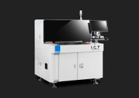
For a buyer whose product mix includes both prototype work and fine-pitch production, the practical arrangement is often a semi-automatic machine for the prototypes and a fully automatic machine for production, with the recipes kept separate. The semi-automatic machine can be a useful training ground, because the operator who has aligned thousands of boards by eye understands the failure modes when the automatic machine mis-aligns. One of the semi-automatic classes worth looking at for this role is the I.C.T P6 semi-auto SMD solder paste printing machine, which is representative of the vision-assisted class; a long-board semi-automatic machine such as the I.C.T 1200 1.2-meter SMD stencil solder printer covers the other end of the size range for buyers who also run long LED boards. Neither machine is a fine-pitch production answer on its own, but both are the natural entry points for the engineering and moderate-volume cases.
A fully automatic inline printer is the production answer for fine-pitch and 0201 work, and the specifications that matter are a short list that can be checked item by item. First, the vision system: it should capture the fiducial sizes the product uses, use a higher magnification for local fiducials, and give the operator a visible image so that a marginal fiducial can be diagnosed rather than guessed at. Second, the table and stage mechanics: they should be capable of the alignment repeatability the budget requires, over a warm-up period, and the machine should be able to document that repeatability rather than assert it. Third, the board support: the machine should offer a programmable support system — a pin nest, a vacuum bed, or a hybrid — with enough resolution that the support density can be set for the buyer's thinnest board.
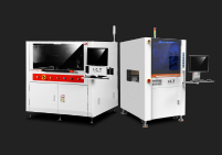
The remaining items on the list concern control rather than mechanics. The printer should allow print speed, squeegee force, separation speed and cleaning interval to be stored in a recipe and reproduced exactly, because those are the parameters that change between products and between paste batches. It should support programmable separation, with a two-stage profile if possible, because separation is where a thin stencil earns its keep. It should have an SPI interface so that deposit measurements can be fed back, even if closed-loop control is not used immediately. And it should have the mechanical and workflow features that make a fine-pitch routine possible: a blade levelling feature, a stencil-tension or stencil-protection interlock, a cleaning system with a change indicator, and a maintenance log that records blade changes and cleaning cycles. A machine that covers this list will hold a fine-pitch budget in production; a machine missing the first three items will not, whatever its headline accuracy figure. One of the fully automatic classes to consider for fine-pitch production is the I.C.T 6534 SMT solder paste printing machine, which represents the inline fully automatic class with a programmable support and vision system; the same class includes variants with different printable areas for different product mixes.
The checklist below is organised by the six contributors to the print budget, so that each item traces back to the mechanism it controls. It is deliberately written as questions to ask, because the answers are what distinguish a machine that will work from one that merely looks suitable on a datasheet. Some items are machine specifications, some are tooling deliverables, and some are workflow features; the value of listing them together is that it exposes the items that a machine-only evaluation would leave to chance.
# | Area | Question to ask | What a good answer looks like |
|---|---|---|---|
1 | Alignment | What is the alignment repeatability measured on real boards, over a warm-up? | A distribution figure with test conditions, not a single number |
2 | Alignment | What is the smallest fiducial the vision system captures reliably? | Stated in micrometres, with the contrast condition |
3 | Alignment | Does the machine re-measure fiducials after a stencil change? | Yes, automatically |
4 | Stencil | How is the frame clamped, and how repeatable is the load position? | A locating feature and a defined clamp sequence |
5 | Stencil | Is there a stencil support ledge or air-bearing for thin foil? | Yes, to keep the foil in the board plane |
6 | Stencil | What stencil thickness and tension can the machine accept? | Down to 0.08 mm foil at 40 N/cm and above |
7 | Squeegee | What blade material and thickness are supplied, and is levelling assisted? | Metal blade, per-side levelling or a force readout |
8 | Squeegee | Is squeegee force programmable and reproducible from a recipe? | Yes, with a defined adjustment range |
9 | Squeegee | What is the blade replacement interval and how is wear tracked? | A cycle count in the maintenance log |
10 | Support | What support systems are available? | A programmable pin nest, a vacuum bed, or a hybrid |
11 | Support | What is the minimum support spacing, and how long does changeover take? | Stated in millimetres and minutes |
12 | Support | Can the support be set by recipe rather than by hand each time? | Yes, ideally with a programmable grid |
13 | Paste | What paste types does the machine's dispensing and cleaning suit? | Type 4 to Type 6 without modification |
14 | Paste | Can cleaning interval and paste volume be set in the recipe? | Yes, per product |
15 | Paste | How is stencil life managed across a shift? | A scheduled clean at the supplier's interval |
16 | Repeatability | Is there an SPI interface, and what does it control? | Data in, parameter adjustment out, with limits |
17 | Repeatability | What is the machine's documented warm-up and drift figure? | A time-to-steady-state figure and a drift number |
18 | Repeatability | Does the machine log blade changes, cleans and calibrations? | Yes, exportable |
19 | Workflow | How are recipes stored, edited and recalled? | A recipe library with controlled edit access |
20 | Workflow | What does the supplier provide for commissioning and first-article qualification? | A documented qualification protocol for fine pitch |
Commissioning a fine-pitch printer is a measurement exercise, and the useful protocol is one that walks the budget rows and confirms each one. It starts with the mechanical checks — print platform parallelism, stencil support plane, blade levelling — measured with a dial indicator or the machine's own diagnostics, because these are the items that cannot be corrected later by a recipe. It then moves to the alignment study: a run of fiducial alignments from cold start through warm-up, plotted as a distribution, which establishes the centre and the spread that go into the budget. It continues with a support study: the same fine-pitch pattern printed with the board in three orientations, compared by SPI, which confirms that the support is holding the board flat rather than merely holding it.
The final stage is the process capability run: at least 30 boards printed with the production recipe, measured by SPI, with a Cpk computed on deposit volume. A Cpk at or above 1.33 on the fine-pitch devices is the target for release to production; below that, the protocol should require the team to walk the budget rows in order rather than to accept the result and hope that production variance is lower than the qualification run's. It is useful to align this protocol with the general equipment acceptance framework — the incoming inspection, the site acceptance and the process qualification — so that the fine-pitch measurements are recorded in the same place as the rest of the machine's acceptance data, and so that the tooling suppliers for stencil and support are drawn into the same exercise rather than being treated as separate purchases. That alignment is the same principle the acceptance framework applies to any solder paste printer, and it is the mechanism by which a fine-pitch line demonstrates that its printer is holding the budget rather than merely promising to.
Talk to an I.C.T fine-pitch and 0201 application engineer
If you are working through the equipment side of SMT stencil printing for fine pitch and 0201 components and would like a second opinion on the tolerance budget for your product, send us the smallest aperture and the finest pitch on the board, the component mix, the board thickness and measured warpage, and the solder paste type you intend to run. We will come back with a worked budget in the same nine-row format used in section 1.2, a stencil thickness and area-ratio recommendation for your smallest aperture, a board support and vision specification matched to that budget, and a shortlist of printer classes that clear the fixed rows rather than the average ones.
We build semi-automatic desktop printers, fully automatic inline printers, LED-optimised long-board printers and dedicated long-board machines, so the recommendation is not tied to a single platform. What the recommendation will do is name the rows of your budget that are actually binding — usually alignment and support — and tell you which machine specification and which tooling deliverable each one demands. The same exercise works for a product that only reaches 0.5 mm pitch and a product that runs 01005, because the budget scales with the component rather than with the machine.
Fine pitch is usually taken to begin at 0.65 mm lead pitch, with 0.5 mm and 0.4 mm as the common production cases and 0.3 mm pitch as the leading edge of standard technology. On the chip side, 0402 is the mainstream fine-pitch passive and 0201 is the step that most lines find challenging: a 0201 chip measures about 0.6 × 0.3 mm, its pad is roughly 0.30 × 0.35 mm, and the paste deposit is under 0.11 mm2 of aperture area. Because the acceptable placement offset on a 0.4 mm pitch device is on the order of 50 µm, the combination of 0201 passives and 0.4 mm pitch leaded devices is the point at which the print has to be engineered rather than set up. The practical way to decide whether SMT stencil printing for fine pitch and 0201 components applies to your product is to take the smallest single aperture on the stencil and the shared aperture-to-wall-area ratio at the thickness you intend to use, and check that the ratio stays above about 0.66.
For 0201 production, no, and the limiting factor is alignment rather than print quality. A semi-automatic printer relies on the operator to load and align the board, and human visual alignment cannot hold the 15–30 µm tolerance that a 0201 product and a 0.4 mm pitch device need, so the deposit pattern is set by how well the operator happened to align that particular board. The machine may print a perfectly formed deposit in the wrong place, which is a failing product rather than a passing one. The exception is engineering and prototype work, where a vision-assisted semi-automatic machine with a good stage can produce usable fine-pitch articles because the human time available per board is high and the volume is low. For production the practical arrangement is a semi-automatic machine for prototypes alongside a fully automatic inline machine for the fine-pitch products, with separate recipes and separate qualification runs.
A 0201 pad of about 0.30 × 0.35 mm needs an area ratio of at least 0.66 to release reliably, and at a standard 0.12 mm stencil thickness the ratio is only about 0.67, which is marginal. Dropping to 0.10 mm raises it to about 0.81 and 0.08 mm raises it to about 1.01, which is why 0201 work is normally run on 0.08–0.10 mm foil. The complication is that thinner foil also means less paste volume on large pads, so a product that combines 0201 passives with large power pads may not tolerate one uniform thickness. The usual answers are a stepped stencil, where the foil is thinned only over the fine-pitch area, or a separate second print for the coarse features. Both decisions belong with the stencil supplier at the design stage rather than at first article, and both should be quoted as part of SMT stencil printing for fine pitch and 0201 components so that the aperture geometry, the thickness and the tension are settled together.
Type 5, with particles up to about 25 µm, is the practical minimum for 0201 and 0.4 mm pitch, and Type 6, up to about 15 µm, is reserved for 01005 and 0.3 mm pitch. Type 4 paste can often handle 0201 apertures if the stencil is stepped so that the foil is thin only over the fine-pitch area, but the large particles in Type 4 will block the smallest apertures and produce intermittent voids, so the choice depends on the smallest aperture in the mix rather than on the largest. Each step finer in the powder costs roughly 10–50% more per jar and demands more careful handling: finer powders absorb moisture faster, dry on the stencil sooner, and have a shorter stencil life. The right answer is to step down only as far as the smallest aperture requires, and to match the cleaning and re-paste interval to the supplier's stencil-life figure rather than to the amount of paste left in the dispenser.
The allowance on a 0.4 mm pitch device is on the order of 75 µm of total offset, which has to cover the printer's alignment, the board's flatness under the print platform, the placement machine's own offset and the reflow self-alignment that can recover some of it. Because the printer's share should be a minority of that allowance, a practical target for the alignment contribution is 25–35 µm of combined accuracy and repeatability, with repeatability mattering more than accuracy for production yield. A machine with a stable 40 µm systematic offset that can be calibrated out is worth more than one with a 10 µm mean and a 35 µm spread, because the spread cannot be compensated. The useful specification to ask about is therefore a distribution measured over many cycles on real boards through a warm-up, not a single best-case accuracy figure measured on a glass plate.
Intermittent failure on a fine-pitch product almost always means one row of the tolerance budget is varying between boards rather than being out of specification on all of them, and the pattern of the variation narrows the candidates quickly. If the failures cluster at one position on the board, look at the support and at local fiducial capture: a loose pin or a marginal fiducial produces exactly that pattern. If they move with the board but stay in the same position relative to it, the cause is in the board or the stencil — warpage, thickness variation or an aperture defect. If they change with the time of day, the cause is paste stencil life, thermal drift or ambient humidity, and the response is a handling routine rather than a printer adjustment. The diagnostic that separates these fastest is to print the same pattern with the board rotated 180°: a defect that stays with the machine is a machine problem, and a defect that follows the board is a board or tooling problem.
Board support is the culprit when the deposits at the centre of the board differ systematically from the deposits at the edges, and when the difference grows as the board gets thinner, longer or more warped. The mechanism is straightforward: the vision system aligns on fiducials at the board corners, but the centre of the board deflects when the print platform pushes it up to the stencil plane, so the centre of the board prints at a different offset from the one the alignment was computed for. The test is to print the same pattern with the same board in three orientations and compare the SPI results; a well-set support gives a consistent pattern, a poorly set one shows a systematic shift that follows the orientation. Support density needs to be specified for the thinnest and most warped board in the product mix, not the average one, because the deflection of a plate under load rises with the fourth power of the support spacing — doubling the gap increases the deflection about sixteen times. On a fine-pitch product the support is part of the print accuracy specification rather than a workshop convenience.
The target for fine-pitch printing is a process capability index of at least 1.33 on deposit volume, with 1.67 or better for the most demanding products; the equivalent process performance index is sometimes quoted where the data is not collected in a controlled subgroup structure. Since the specification limits for a 0201 deposit might be ±30% of nominal, a Cpk of 1.33 implies a standard deviation of only about 7–8% of nominal, which is demanding but routinely achievable on a well-set-up line. The measurement discipline matters as much as the number: use an SPI system, measure the same fixed inspection window that contains the fine-pitch and 0201 devices on every board, and run at least 30 to 50 boards after each product change before computing the index. The most useful output is not the single number but the trend, because a gradual drift points at paste stencil life, a step change at a stencil or board change points at tooling, and an increase in scatter with a stable mean points at the support or the blade.