English
 Views: 0 Author: Elsa Long Publish Time: 2026-10-14 Origin: Site


Short answer: choosing a Solder Paste Printing Machine for large PCB and long board production is not the same exercise as choosing one for a standard 250 × 150 mm board, and the difference is not simply "a bigger machine". What changes is the set of constraints that stops mattering and the set that starts to dominate. On a standard-format board the limiting factors are print accuracy, cycle time and paste handling, all of which are settled inside the machine enclosure. On a large or long board the limiting factors move outward to three interfaces the machine must satisfy before accuracy is even in question: the printable area and stencil frame, which is a hard geometric gate; the board support system, which decides whether a long panel prints flat or bows through the stencil; and the conveyor and handling envelope, which decides whether the board can travel to and from the printer without sagging, misaligning or being loaded by hand. A printer that is accurate on a 200 mm board can be unusable on a 1,200 mm board not because its print head is wrong but because none of those three interfaces was specified for that length. Get the interfaces right and mid-class automation prints cleanly at length; get them wrong and a high-accuracy machine produces a bowed, off-register print on every panel.
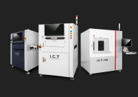
This guide is organised as a format ladder rather than a feature list, because that is how the constraint set actually changes as boards grow. Section 1 defines the four format bands — standard, large, long and ultra-long — and explains why width and length are two separate engineering problems that fail in different ways. Sections 2 to 5 then walk the four interfaces that the format ladder stresses in order: printable area and stencil frame, board support, stencil and squeegee over long spans, and conveyor and handling. Section 6 covers the special board types that sit outside the ladder — LED strip and light-bar panels, multi-up arrays, aluminium-backed and thick-copper boards. Sections 7 and 8 turn the diagnosis into a printer-class match and a pre-purchase checklist. To see the machine families this guide draws from, start at our I.C.T solder paste printer product hub, which lists the semi-automatic, fully automatic inline and long-board classes; this article assumes you have already decided that your boards are large or long and focuses on what that decision demands of the equipment.
Table of Contents
What "large" and "long" actually mean in solder paste printing
Printable area and stencil frame — the first hard constraint
Board support for wide and long panels — where warpage decides yield
Special board types — LED strips, panels and exotic substrates
The word "large" is used loosely in SMT procurement, and the looseness hides a real engineering boundary. A buyer who says "we run large boards" might mean a 400 mm industrial controller that is merely wider than a standard magazine, or a 1,200 mm LED light-bar panel that will not fit through a conventional printer at all. Those two applications sit in different format bands, they stress different parts of the printer, and the machine that solves one may be incapable of the other. Before comparing models, the buyer has to fix two numbers — the maximum board width and the maximum board length — and then place those numbers on a format ladder that maps directly onto machine specification classes. Everything in this guide is downstream of that placement, because the format band, not the feature list, decides which three or four specifications will actually restrict the purchase.
This section does three things. First it defines a four-band format ladder in terms of real board dimensions and real applications, so that two engineers can agree on what "large" means in a conversation. Second it explains why width and length are two separate problems: width stresses the conveyor, the squeegee span and the stencil frame equally, while length stresses transport, support spacing, stencil tension and squeegee travel, and the two failure modes are nothing alike. Third it names the four physical constraints — warpage over span, stencil tension over frame length, squeegee deflection over stroke, and transport support over conveyor length — that begin to dominate as the ladder is climbed, and it shows how each one converts into a machine requirement rather than an operator skill.
The four bands used throughout this guide are defined by the maximum board dimension a printer has to accept, not by the board area, because it is the maximum dimension that sets the frame and transport requirements. Standard format runs up to roughly 350 × 250 mm: this is the classic SMT board, served by any mainstream fully automatic printer, and its constraints are print accuracy and cycle time. Large format covers boards from roughly 350 mm up to about 600 mm in the long dimension and up to about 400 mm in width — industrial controllers, power modules, communication equipment, larger multi-up panels — and here the printable-area specification and the board-support design start to matter more than raw speed. Long format covers boards from about 600 mm to 1,200 mm, dominated in practice by LED light bars, LED strip panels and long slim controllers; this band is where conveyor support, stencil tension and squeegee stroke become the governing constraints, and where a purpose-designed long-board machine separates from a stretched standard one. Ultra-long format runs beyond 1,200 mm up to about 1,500 mm and a little further for specialised LED and linear-lighting work; at this band almost every interface is custom — stencil frame, support bed, conveyor and handling — and the selection question changes from "which printer" to "which printer plus which handling and tooling package".
Format band | Max long dimension | Typical max width | Representative applications | Constraint that dominates first |
|---|---|---|---|---|
Standard | up to ~350 mm | up to ~250 mm | Consumer modules, small controllers, standard panels | Print accuracy, cycle time, paste handling |
Large | ~350–600 mm | ~250–400 mm | Industrial control boards, power modules, comms equipment, larger multi-up panels | Printable area, stencil frame size, board support |
Long | ~600–1,200 mm | ~250–500 mm | LED light bars, LED strip panels, long slim control boards | Board support over span, stencil tension, squeegee stroke, conveyor support |
Ultra-long | ~1,200–1,500+ mm | ~250–600 mm | Linear lighting, long LED panels, specialist backlighting and signage boards | Custom stencil frame, custom support bed, handling and transport package |

The practical use of the ladder is that it stops buyers from comparing machines on the wrong axis. Two printers with identical cycle times and identical accuracy figures can differ by a factor of three in price once the long dimension passes about 600 mm, because the length drives structural stiffness, frame size and transport design in ways that have nothing to do with the print head. Placing your worst-case board on this ladder before the first quotation prevents the most common large-board procurement error: buying a machine that meets the accuracy requirement, meets the cycle-time requirement, and still cannot physically accept the board or hold it flat enough to print.
Width and length are usually discussed together, but they stress different subsystems and they fail in different ways. Increasing width moves the conveyor rails apart, lengthens the squeegee blade span, widens the stencil frame and increases the printed area that must be cleared uniformly; the failure mode of excess width is uneven squeegee pressure across the blade, edge-to-centre variation in paste deposit, and a conveyor whose rails must be adjusted symmetrically without skewing. Increasing length does something quite different: it increases the unsupported span the board must bridge, lengthens the squeegee travel, makes stencil tension loss more consequential, and stretches the transport path; the failure mode of excess length is board sag and warpage under the stencil, increasing print variation along the board's length, trailing-edge smearing when the board sags into the stencil at the end of the stroke, and the need for a conveyor and support layout that holds a long panel at several points rather than two.
The two problems also demand different remedies, which is why a printer described as "large-format" may not be a long-board machine and vice versa. Width is largely a matter of frame size and blade span — a printer with a wide enough frame and a stiff, straight squeegee can cover width almost as easily as a smaller machine, provided the conveyor rails adjust squarely. Length is a matter of support and stiffness: the board has to be held flat along its entire length, the stencil has to stay taut across a longer frame, the squeegee has to traverse without deflecting, and the board has to enter and leave without sagging. A buyer who needs 1,200 mm of length and buys a machine chosen for 500 mm of width will discover that width was never the problem — the long panel sags between the rails, the stencil loses tension at its centre, and the trailing edge prints differently from the leading edge. The selection checklist for the two cases therefore diverges early: for width, interrogate frame size, blade span and rail squareness; for length, interrogate support spacing, stencil tension specification, squeegee stroke and transport support. Buyers who have not yet decided which of the two is binding should first run the general SMT solder paste printer selection guide for production lines to settle the machine class, then return here to size the long-board specifics.
Four physical effects govern long-board printing, and each one converts into a specific machine requirement rather than into operator technique. The first is warpage over span: the deflection of a board under its own weight and print force grows with at least the cube of the unsupported span, so a panel that prints flat across 300 mm can bow noticeably across 900 mm unless the support layout is designed for the longer span. The requirement this produces is support spacing — the maximum distance between support points along the board's length — and a printer that cannot place support at short intervals along a long board will print a bowed board no matter how skilled the operator. The second is stencil tension loss over frame length: a longer stencil frame, especially an aluminium-framed mesh, sags more at its centre for the same applied tension, and once the mesh sags it contacts the board unevenly and squeegee force has to be raised, which increases deflection further. The requirement is a frame and mesh specification — heavier frame section, higher minimum tension, sometimes a double-frame or reinforced design — chosen with the board length in mind.
The third constraint is squeegee deflection over stroke: a longer blade span bows more under the same downward force, so the paste deposit thins at the blade's centre relative to its ends unless the blade is either stiffened, supported differently, or run at a reduced pressure that compensates. This is why long-board printing is often specified with a segmented or dual-blade squeegee, and why a squeegee proven on a 250 mm board cannot simply be extended to 1,200 mm and run at the same pressure. The fourth constraint is transport support over conveyor length: a long board exiting the printer has to be supported across its whole length as it transfers, or its overhanging end sags, drags on the rails and misaligns at the next station; this drives the conveyor design, the number of support points, and often the handling arrangement — single-piece transfer rather than magazine, or an intermediate conveyor section. Each of these four constraints appears again in the sections that follow, expressed as a machine specification rather than as a physical effect. Reading them as a set explains why long-board selection is a systems exercise: they interact, they are all length-dependent, and satisfying one without the others produces a printer that works in the demonstration and fails on the customer's longest panel.
A fifth practical point sits alongside the four: the constraints above scale with the worst-case board, not the average. A line that runs mostly 300 mm boards and occasionally a 1,000 mm panel must be specified for the 1,000 mm panel, because the printer cannot partially satisfy a support or tension requirement. This is why the first step of any large-board project is to identify the single longest and widest board the line will ever run, and to size every interface from that board downward. Lines that specify from the average board and then meet the outlier discover the gap at the worst moment — during the customer's first production run of the longest product.
Printable area is the one specification that is genuinely binary: a printer either accepts the board or it does not, and no amount of process tuning compensates for a board that is larger than the printable envelope. Because brochure printable-area figures are quoted in different ways — sometimes as a maximum board size, sometimes as a squeegee print area, sometimes as a conveyor width — the translating work of this section is to convert the buyer's board dimensions into three separate machine numbers and confirm that all three clear the board. The failure mode of getting this wrong is not a degraded print; it is a machine that arrives, is commissioned, and then cannot run the product the project was justified on. That outcome is avoidable with a short set of measurements done before the order, which is what the subsections below provide.
The section is organised around three questions. How is a board dimension translated into a machine specification, and which three numbers have to be checked rather than one? How much margin does a large board need beyond its nominal size, and how does that margin interact with the stencil frame the board implies? And what are the specific traps that appear when the board is very long — cases where the printable area is adequate but the frame, the stroke or the conveyor still fails? The answers are given as numbers and tables so that they can be used directly in a specification sheet or a purchase enquiry.
A board's outer dimensions must clear three distinct machine specifications, and quoting only the printable area is the most common large-board specification error. The first number is the printable area: the region over which the printer can actually deposit paste, which is normally smaller than the machine's maximum board size because the conveyor rails and clamp consume some of the envelope. The second is the stencil frame size the machine accepts: a printer may print across a 500 mm board but only accept a standard 736 × 736 mm frame, in which case the stencil for a longer board cannot be clamped at all, since the frame must be larger than the board plus a border. The third is the conveyor width range: the board must fit between the rails, and for long boards the rails must also be able to support the board along its length rather than at two points, which is a transport specification rather than a width specification.
The working rule is to record the maximum board length and width, add the process margin described in the next subsection, and then check all three numbers — printable area, accepted frame size and conveyor range — against the candidate printer, treating any one of them as a veto. A fourth number is worth adding for long boards: the maximum squeegee stroke, which must exceed the board length plus a lead-in and lead-out so that paste is deposited across the full board and not merely across its centre. A machine can pass the printable-area check and still be unable to print a long board because its stroke is shorter than the board, and stroke is not always listed in the same place as printable area. Buyers who ask for all four numbers on one line of the quotation avoid the situation where three specs pass, one fails, and the failure is only discovered in commissioning.
Large and long boards need margin beyond their nominal dimensions, and the margin is not a rounding nicety — it is consumed by real process needs. The stencil must overhang the board on every side by enough material to carry the apertures' support and to clamp cleanly, and a frame that is only just larger than the board leaves no room for the mesh border that holds tension; a practical minimum is a border of 25–50 mm beyond the board edge on each side, and more for long frames where tension loss is greater. The conveyor must also accept the board with a small clearance so that the rails can support it without pinching or dropping it, and the board's leading edge must reach the squeegee start position and its trailing edge must clear the squeegee end position, which together require roughly 20–40 mm of stroke margin at each end. Finally, the printable area itself should exceed the board by the alignment window: the machine has to move the board a few millimetres to find fiducials and align, and a board that exactly fills the printable area has no room for that motion.
The consequence for the stencil frame is direct: the frame size is a function of the board length plus the border, not of the board alone. A 1,000 mm LED panel with a 40 mm border requires a frame at least about 1,080 mm long inside its clamps, which rules out machines that accept only standard 736 mm or 800 mm frames regardless of their printable-area figure. This is why the stencil frame specification should be confirmed in writing alongside the printable area, and why a trial stencil for the longest board is worth making before the printer order is finalised — it tests the frame, the tension and the clamp at the same time. Buyers who treat the frame as an afterthought discover, at the worst possible moment, that the printer they chose can print a long board in principle but cannot hold the stencil that long board needs.
Three specific traps appear repeatedly once boards pass about 600 mm in length, and each one defeats a printer whose headline specifications looked adequate. The first is the frame trap: the printable area is large enough and the conveyor is wide enough, but the machine's maximum stencil frame is a standard size smaller than the board needs. This is detected only by checking the frame specification explicitly, and it is common on machines marketed for larger boards whose frame handling was not upgraded with the print area. The second is the stroke trap: the printer can clamp the stencil and accept the board, but its squeegee stroke is shorter than the board's long dimension, so paste is deposited across only part of the panel and the ends are left without paste; the mask is usually that the advertised cycle time and printable area both pass, and only the stroke figure reveals the limit. The third is the support trap: printable area, frame and stroke all clear the board, but the support bed cannot place support points near enough together along the board's length, so the long panel bows between the few available points and prints with a length-wise deposit gradient — thin where the board touches the stencil, heavy where it has been pushed down.
All three traps share a diagnostic: they are invisible in a printable-area comparison and visible in a specification worksheet that records frame size, stroke length and support spacing alongside the print area. The remedy is procedural rather than technical — build the worksheet before the quotation, and require the supplier to state each of the four numbers rather than a single "maximum board size". Buyers who do this consistently report that the worksheet also shortens the technical discussion, because it forces the comparison onto the same four axes for every candidate machine and makes an unstated number conspicuous. For long-board projects specifically, the worksheet should be completed for the worst-case board, not an average one, since the traps are all length-dependent and a machine that passes on the average board can still fail on the longest.
On a standard board the support system is invisible: the board is stiff enough, short enough and thick enough that almost any support arrangement holds it flat, and operators rarely think about it. On a wide or long board the support system becomes the single largest determinant of print quality, because a panel that is not held flat does not simply print slightly worse — it prints a deposit that varies systematically from one end to the other, and the variation is a function of the board's geometry rather than of the paste or the squeegee. This is why experienced long-board buyers interrogate the support system before they interrogate the print head, and why a machine with a modest accuracy specification but an excellent support bed will out-print a machine with a better head and a poorer bed on long panels. The support system is what converts a nominally flat board into an actually flat board at the moment of printing, and at length that conversion is nothing like automatic.
This section covers the support question in three parts. First it explains the mechanics of why support matters so much more at length — the relationship between unsupported span and deflection, and why that relationship makes long boards behave qualitatively differently from short ones. Second it compares the four support technologies used on large-board printers and states when each is appropriate, with the trade-offs in setup, flexibility and repeatability. Third it separates the two roles a support system plays — edge support and centre support — and shows how they must be designed together, because a system that does one well and the other poorly produces a characteristic and recognisable defect pattern.
The deflection of a board under a distributed load grows rapidly with its unsupported span. For a panel simply supported at two edges and loaded uniformly, the maximum deflection is proportional to the fourth power of the span divided by the cube of thickness; even treating the board as stiffer than that idealisation, the practical consequence is that a board which is comfortably flat across a 300 mm span can bow visibly across a 900 mm span for the same load and the same thickness. Under a stencil printer the load is not uniform and not small: the squeegee presses the stencil down against the board, the board presses back, and any unsupported region between the rails is free to deflect downward. The board therefore does not sit flat on the stencil; it sags away from the stencil in the unsupported regions and contacts it in the supported regions, and paste is deposited according to that contact rather than according to the stencil apertures alone.
The defect this produces is characteristic: paste deposit is heavy where the board contacts the stencil and light or absent where it has sagged away, so the print shows a length-wise or width-wise gradient — often bright, well-formed pads near the support points and starved pads between them, with a trailing-edge smear where the board springs back into the stencil at the end of the stroke. The failure mode is easy to misdiagnose: because the deposit variation follows the board's geometry rather than the squeegee direction, it looks like a stencil or paste problem and leads to changes in squeegee pressure and speed that make it worse rather than better. The correct response is more or better support, and the sizing rule is that the maximum unsupported span along the board's length should be kept short enough that the board's own stiffness holds it flat under print load — a figure that depends on board thickness and material but that in practice means support points every 100–150 mm along a long board, and more frequently for thin panels.
Four support technologies appear on large-board printers, and none is universally best; the right choice depends on board variation, thickness and batch size. Magnetic support pins are individual posts placed on a magnetic platform bed at positions under the board; they are fast to reposition by hand, they suit frequent product changes, and their main limitation is spacing — pins cannot always be placed as densely as a long thin board needs, and their height must match the board's underside clearance. Multi-point pin nests are arrays of spring-loaded or adjustable pins that support a board along its whole length at fine pitch; they hold long boards well and reset quickly if the array is programmable, but they are less tolerant of boards that carry tall bottom-side components. Vacuum beds hold the board by suction across a porous or channeled platform, which flattens mild warpage without mechanical contact and is excellent for thin, flexible or very long boards; the limits are that they pull the board down only where vacuum reaches, and that they need board sealing and enough pump capacity for the panel area. Dedicated fixtures are machined nests cut for one board outline; they give the flattest, most repeatable result and are the standard choice for high-volume fixed products, but they cost one fixture per product and are impractical for a job shop.
Support technology | Best for | Typical reset time per product | Main limitation on long boards |
|---|---|---|---|
Magnetic support pins | Frequent product changes, moderate boards | 2–10 min | Pin spacing may be too coarse for thin/long panels; height matching needed |
Multi-point pin nest (spring or programmable) | Long boards needing fine-pitch support | 1–5 min if programmable, more if manual | Conflicts with tall bottom-side components; programming needed |
Vacuum bed / channeled platform | Thin, flexible or very long boards; mild warpage | Under 1 min | Needs sealing and adequate pump capacity; less effect where vacuum cannot reach |
Dedicated machined fixture | High-volume single product; flattest result | Fixture change: 10–30 min | One fixture per product; impractical for high mix |
The selection rule is to match the technology to what varies. If the board outline changes often and the boards are moderately stiff, magnetic pins or a programmable pin nest give the best balance and keep reset under a few minutes. If the boards are long, thin or flexible — the LED strip and light-bar case — a vacuum bed alone is often insufficient and is usually combined with pins, because vacuum flattens the centre while pins define the datum. If one product runs in volume and flatness is critical, a dedicated fixture returns the best yield and the highest cost per product. In every case the specification to confirm with the supplier is the maximum support density the bed allows along the board's long axis, because that number, not the bed's area, decides whether a long panel can be held flat.

A board is held in a printer by two systems acting at once: the edge support — the conveyor rails or clamps that define the board's plane and its height — and the centre support — the pins, nest or vacuum that prevent the middle of the board from sagging. Long-board printing fails when these two are designed or set independently. If the edges are held firmly and the centre is unsupported, the board bows downward in the middle and prints a starved centre. If the centre is over-supported and the edges are loose, the board is pushed upward at the centre and prints heavy in the middle with smeared edges. The two must define a common plane, which is why long-board machines usually combine an edge rail or clamp with a height-adjustable centre support that can be set to the same plane as the rails, and why operators need a reliable height-setting procedure rather than trial and error.
Two further points matter for long boards. First, the support plane must be adjustable for board thickness as well as board length: a 0.8 mm LED strip panel and a 2.0 mm control board need different centre-support heights to sit in the same edge plane, and a machine whose support height is fixed to one thickness will hold one product well and the other badly. Second, support must extend to the board's overhanging regions during transport, not only under the print area, or the leading and trailing ends sag as the board enters and leaves; this is a conveyor and handling issue as much as a support issue and is covered in section 5. On lines that run both long and short boards, the support system also has to reset quickly, since the same machine may print a 1,000 mm panel in the morning and a 300 mm module in the afternoon — a changeover-load consideration that our guide to selecting an SMT stencil printer for high-mix low-volume production treats in detail, and which on a mixed line can make support flexibility more valuable than support density alone.
The stencil and squeegee are where the printer's mechanics meet the paste, and both behave differently over a long board than over a short one. A longer stencil frame loses more tension at its centre for the same applied load, a longer squeegee blade deflects more under the same pressure, and paste g-forces and rheology act over a longer stroke; the result is that the printing window — the range of pressure and speed that produces an acceptable deposit — narrows as board length grows. Buyers who specify a long-board machine on printable area alone often find that they can hold the board and clamp the stencil but cannot print a uniform deposit across the full length without either reducing pressure to the point of skipping at the ends or raising it to the point of flooding at the centre. This section explains why that happens and what machine and stencil features widen the window again.
The section covers the three parts of the long-span problem in turn. First the stencil itself — frame design, mesh tension and how tension loss over a long frame changes the required specification. Second the squeegee — stroke length, blade stiffness and the pressure distribution question, with the parameters that long-board printing typically needs. Third the cleaning and paste-handling side of a long stencil — how a longer mesh changes under-stencil cleaning, paper consumption and the way paste is recovered or discarded between products. Together these three parts define what a long-board stencil package should contain, and they explain why a stencil made for a standard board cannot simply be scaled up.
A stencil's job is to present a flat, taut aperture plane to the board, and over a long frame that job becomes harder. Aperture geometry and stencil thickness for a given pad are set by the standard stencil design rules collected in IPC-7525 (Stencil Design Guidelines), which long-board stencils follow for aperture area ratios exactly as standard boards do — the difference is not the aperture but the frame that carries it. Mesh tension is set when the stencil is made by stretching the mesh over the frame and gluing it down; a longer frame, especially an aluminium one, sags more at its centre for the same tension because the frame itself and the longer mesh span both deflect. Once the mesh sags, the gap between stencil and board is no longer uniform, squeegee force has to be raised to press the stencil down onto the board at the centre, the frame deflects further, and the deposit becomes inconsistent along the length. The practical remedies are a heavier frame section, a higher specified minimum tension measured with a tension gauge, a double-frame or reinforced design for very long stencils, and sometimes a stiffer mesh thickness. All of these are stencil specifications, not printer specifications, which is why the stencil and the printer must be specified together for a long-board project.
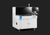
The tension specification should be written as a minimum acceptable value in newtons per centimetre measured after the stencil has been made, with an acceptance test at goods-in and a re-measurement policy after a defined number of print cycles. Long stencils lose tension faster than short ones, so a stencil that is acceptable when new can drop below the working threshold after a few thousand cycles; without a re-measurement policy the loss shows up as a slow drift in print quality that is attributed to the machine. Frame size, as noted in section 2, is set by the board length plus a border, and a stencil for a 1,000 mm board with an adequate border and a reinforced frame is a substantially larger and heavier article than a standard stencil — which is why long-board stencils are usually quoted as a separate line item and why lines running long panels often keep two stencils per product so that one can be in tension recovery while the other runs. Machines in the long-board class, such as the I.C.T 1200 1.2-meter SMD stencil solder printer, are dimensioned around this stencil envelope rather than around a standard frame with extra print area.
The squeegee is where pressure is applied, and over a long blade the applied load does not translate into uniform pressure. A blade that is long enough to span a 1,000 mm board bows under its own stiffness when pressed down, so the pressure at the blade's centre is lower than at its ends unless the blade is stiffened or the pressure is raised; raising the pressure increases the bow and eventually floods the centre while the ends are still starved. The printing window therefore narrows with blade length, and the features that widen it are a stiffer blade material or a blade with a thicker cross-section, a segmented or dual-blade arrangement that applies pressure in sections, a holder that supports the blade along more of its length, and in some designs a pressure profile that is adjusted across the blade. Long-board printers are specified with a maximum squeegee stroke that exceeds the board length and with a blade span matched to the maximum board width, and both numbers must be checked against the board — the stroke trap from section 2.3 is exactly a squeegee that is too short to traverse the board.
Long-board print parameter | Typical setting/requirement | Why it differs from a standard board |
|---|---|---|
Squeegee stroke | Board length + 20–40 mm lead-in and lead-out each end | Stroke must clear the whole board; short strokes leave the ends unprinted |
Blade span and stiffness | Span ≥ max board width; stiffer or segmented blade for wide boards | Long blades bow; pressure at centre drops relative to ends |
Squeegee pressure | Lower and more uniform than standard; profile-adjusted where available | Higher pressure amplifies blade bow and floods the centre |
Squeegee speed | Reduced over long strokes to keep paste rolling ahead of the blade | Paste rheology acts over a longer stroke; too fast causes skips at the tail |
Snap-off separation | Slower and more controlled over long stencils | Long mesh releases less uniformly; fast separation pulls paste |
Under-stencil cleaning | Longer paper advance per wipe; more frequent cadence on long boards | Longer stencil contact area picks up more residue per print |
The practical consequence is that long-board printing is usually slower per stroke than standard-board printing, and buyers should expect it. Squeegee speed is reduced to keep paste rolling ahead of the blade over the longer stroke, pressure is reduced and made more uniform to avoid centre flooding, and snap-off is slowed to release the longer mesh evenly. These choices lengthen cycle time, so a long-board machine's realistic throughput should be estimated from a long-board cycle rather than from a standard-board datasheet figure; our guide on how to estimate solder paste printer cycle time and throughput shows how to build that estimate from the per-station budget rather than from the brochure number, which matters more on long boards because the squeegee and separation stations grow with board length.

Under-stencil cleaning scales with stencil area, and a long stencil has far more area to clean per cycle than a standard one. Each print leaves residue on the underside of the mesh — paste squeezed through apertures and deposited on the stencil surface — and the wipe that removes it must travel the full length of the stencil, so both the paper consumption per wipe and the time per wipe increase with board length. The selection-relevant figures are the cleaning system's paper roll capacity, the solvent reservoir volume, the maximum wipe length and the number of wipes per cycle. A machine sized for standard boards may have a paper roll that lasts a shift on small boards and only an hour on long ones, forcing frequent reloads and introducing a consumable-driven stoppage into a long-board line where the printer is already the bottleneck.
Paste handling also changes over a long stencil. The paste bead that the squeegee rolls ahead of it must be large enough to cover the board's length without running dry before the stroke ends, and paste left on a long stencil at the end of a run is a larger absolute quantity than on a short one, so recovery or discard decisions have more material consequences. Long-board lines therefore tend to specify a larger paper roll, a bigger or dual solvent reservoir, and a cleaning cycle that can be programmed for length rather than only for count. As with the stencil itself, these are consumable-side specifications that determine total cost of ownership rather than headline performance, and they belong in the same worksheet as the printable area and stroke figures. A long-board printer that passes every geometric check but is refilled twice a shift is a printer that loses output to its cleaning system, which is a failure mode worth measuring before purchase rather than after.
The conveyor and handling envelope is the third interface that has to be specified for a long-board printer, after printable area and support, and it is the one most often treated as an afterthought. On a standard board the conveyor is the part of the machine that nobody thinks about: rails are close, the board sits between them, and the loading can be magazine or single-piece without affecting the design decision. On a long board the conveyor and the loading arrangement define whether the board reaches the print area at all, whether it stays flat while it does, and whether the downstream station can accept it once it has been printed. Many long-board failures that look like printing problems are in fact transport problems: the board sags on entry, the leading edge snags on a misaligned rail, or the printed board cannot be handed off without a second operator. The conveyor and handling design is therefore part of the machine specification, not a peripheral convenience.
This section addresses the three transport decisions a long-board buyer has to make: how the conveyor is set up for width and length, how the board is loaded and unloaded, and whether the printer runs inline with the next station or as an offline station with a buffer. Each decision has a default for a standard board and a different default for a long board, and the differences are usually visible only after the longest board has been on the conveyor for a few hours. The section closes with a worked sense check of when an inline long-board machine is the right answer and when a purpose-built offline long-board machine with its own loading bay is.
Conveyor width on a long-board printer has two roles. The first is to adjust the rail spacing to the board width, with enough travel to cover the widest product the line runs; this is the obvious role and is what most conveyor specifications describe. The second is to support the board along its length, which is less often described and is the role that fails on long panels. The interface height and the mechanical handoff between stations follow the SMEMA convention (the Surface Mount Equipment Manufacturers Association standard that fixes conveyor transfer height and the handshake signals between machines), and on a long-board line SMEMA compliance is necessary but not sufficient: it guarantees that the printer and the next machine agree on where the board's edge sits and on when it may be transferred, but it says nothing about how much of a long board is supported while it travels. A conveyor whose rails only support a board at the entrance and exit of the print area leaves the board's middle unsupported between the rails, and over a long span that middle sags under its own weight. The remedy is a conveyor that either extends a continuous support surface under the board along its length, or adds intermediate support points that move with the board, and the choice between them is what distinguishes a long-board conveyor from a standard one.
Edge support interacts with the centre support discussed in section 3.3: the conveyor rails define the board's plane and the centre support prevents sag between them, and the two must agree on the same plane. Long-board conveyors often provide a third role — a width-adjustment that is driven rather than manual, so that the operator does not have to re-set rail width for every different board, and the adjustment can be saved as part of the recipe. This matters because a line running LED light bars in many lengths but a common width may still benefit from automatic rail setting, since manual setting introduces both time and an opportunity for asymmetric adjustment that biases the print. Buyers comparing conveyors should ask for the rail-width adjustment range and the type of adjustment (manual, indexed, motorised), the maximum unsupported span between rails at the widest setting, and whether support pins can be programmed as part of the recipe rather than positioned by hand.
Loading a long board into a printer is more difficult than loading a standard one, and the loading arrangement is a major determinant of who can run the machine. Magazine loading — boards arriving in a slotted carrier and indexed one at a time into the conveyor — is efficient for short boards but impractical for long ones, because the magazine itself becomes very long and the indexing tolerances accumulate over the magazine's length. Single-piece transfer — the operator placing one board on the conveyor at a time — is slower but more flexible, and for long boards is often the only practical option. Some long-board printers add an intermediate handling arrangement: a long loading table that supports the board while it is positioned, then transfers it onto the conveyor rails as a single piece; this is the format most LED light-bar lines use, because it lets the operator or an automatic loader place a 1,200 mm panel accurately without holding its weight across its full length.
The handling decision interacts with the rest of the line. If the printer is inline with the next station, the output end of the printer must hand the long board off in a way the downstream station accepts, which usually means either a continuous conveyor that runs through both, or an output buffer that supports the board until the next station can take it. If the printer is offline, the printed boards have to be stacked, dried or moved manually, which is itself a handling problem for a 1,200 mm panel. Buyers should specify the loading arrangement alongside the machine, because a printer that meets every printing specification and forces an awkward loading sequence loses throughput to handling rather than to printing. Long-board semi-automatic machines, such as the I.C.T P6 semi-auto SMD solder paste printing machine in its desktop configuration, are often chosen precisely because they accept single-piece loading and let the operator set up long boards without a magazine, which is a real advantage on LED panel lines that run short batches of long boards.
The default in modern SMT is to inline the printer with the next station (typically a pick-and-place) and let the board flow through. For long boards the inline default starts to break down. The longer the board, the harder it is to transport cleanly between stations: the overhanging end sags, the conveyor edges need to be lined up across multiple machines, and a stoppage in one station can hold a long board over multiple stations at once. Inline long-board machines therefore need careful conveyor handoff, often a dedicated long-board buffer between the printer and the pick-and-place, and agreement between the two stations on handling and timing. Offline printing — the printer as its own station with manual or semi-automatic placement of boards into and out of the printer — is a deliberate choice that gives up some throughput in exchange for simpler handling and more flexibility on product mix.

The decision rule is short. If the line runs one or a few long-board products in volume and the next station can be set up to receive them, inline is right and the throughput gains over offline are real. If the line runs many long-board products in small batches, or if the next station cannot easily be configured for long boards, offline is right and the throughput loss is smaller than the handling cost of forcing inline. Buyers should ask the printer supplier to demonstrate loading and unloading at the longest board on their floor — not on a demonstration board — and to confirm the cycle-time impact of long-board loading. The realistic cycle-time figure, rather than the brochure cycle-time figure, is the input to the throughput estimate produced by our how to estimate solder paste printer cycle time and throughput framework, and for long boards it is meaningfully lower than the brochure number because the squeegee stroke and the cleaning cycle both grow with length.
Outside the standard format ladder sit a set of board types that need the long-board specification but in a particular way. LED light bars and strip panels, large multi-up arrays, aluminium-backed boards for lighting and power, thick-copper power boards, and flex or flex-rigid boards each impose their own additional constraints on top of the long-board specification, and a printer that is right for a generic long board is not automatically right for any of them. This section describes the most common special cases so that a buyer who knows the board type can read the relevant subsection and add the extra specification to the worksheet rather than discovering the gap at the customer's first production run.
The section covers three cases. The first is the LED light-bar and strip-panel case — by far the most common long-board application — and the specific characteristics of the LED format: long and narrow, often thin, often with a white solder mask and reflective features that show printing defects more readily. The second is the large multi-up array and oversized panel case, where the long dimension comes from the panel rather than from the board and the constraint is panel handling rather than per-board spec. The third is the exotic-substrate case — aluminium, thick copper, flex — where the substrate behaviour, not just the size, changes the printer's requirements. Each is described in terms of the extra machine specification it implies.
LED light bars and strip panels are the application that drives most long-board printer purchases. The format is typically 300–1,500 mm long, 60–250 mm wide, 0.8–1.6 mm thick, often with a white solder mask that makes paste deposition defects very visible, and with pads designed for 5630, 3030 or 2835 LED packages on a long thin board. The constraints this places on the printer are the four described above, but with some specifics. Length drives the frame, support and squeegee as for any long board; the narrow width simplifies squeegee span and stencil frame size; the typical board thickness (0.8–1.6 mm) makes warpage over a 600 mm span a real risk and forces good support; the white solder mask and reflective pads make under-prints, over-prints and bridging visible on first article. LED lines therefore place a high value on first-article cleanliness, which argues for machines with good alignment repeatability and reliable cleaning cadence.
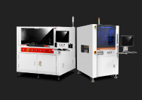
The product class that suits LED strip production is a purpose-designed long-board machine, not a stretched standard one. Online machines configured for LED throughput, such as the I.C.T 5134 online fully automatic solder paste printer for LED, are built around the LED format with conveyor and frame geometry that suit light-bar lengths, while dedicated long-board machines such as the I.C.T 1200 1.2-meter SMD stencil solder printer are aimed at the upper end of the LED and linear-light-size case at around 1,200 mm. The buyer decision between online and offline on LED lines is usually driven by downstream handling: pick-and-place machines that accept long panels inline are not common, and many LED lines prefer offline printing followed by a manual or semi-automatic placement step. Buyers should evaluate the loading arrangement, the support reset time between LED SKUs of different length, and the first-article inspection capability rather than the cycle time alone.
The second long-board case is the oversized multi-up panel, where the panel itself is very large but the individual boards within it are standard sized. Examples include large power-supply panels, industrial controller arrays, and display backlight panels. Here the long dimension is the panel rather than the unit board, and the constraint is panel handling and transport — the panel must move through the printer, be supported, be cleaned under, and exit cleanly. The machine requirements are similar to LED strip printing in terms of printable area and stroke, but the support layout is different because the panel can usually be supported on its carrier or on a panel frame, and the stencil is sized for the panel, not for an individual board.
Selection-relevant differences from LED strip printing are the panel's typical carrier (often a rigid pallet or a routed break-away carrier), the support arrangement (often a panel frame that holds the entire panel rather than pins under individual boards), and the squeegee direction (often set by the panel layout rather than the board). These are specific to the panelisation strategy and should be discussed with the supplier as part of the worksheet. The dimensions to confirm are the maximum panel size, the maximum panel weight, and whether the machine accepts the panel carrier as well as the bare panel. A printer that accepts the bare panel but not its carrier forces the customer to depanelise before printing, which is a real production cost that a long-board worksheet should expose before purchase rather than after.
The third case is exotic substrates, where the material behaviour changes the printer's requirements beyond simple size. Aluminium-backed boards (used in high-power LED and lighting) warp more than FR-4 of the same dimensions and benefit from vacuum support and a heavier support pin layout; they also have different thermal behaviour under the squeegee and may need paste rheology adjustments rather than machine changes. Thick-copper boards (used in power electronics) are stiffer but heavier and require support that can carry the weight without deflection of the pins or the platform; they are usually run at lower squeegee speeds to keep the paste rolling. Flex and flex-rigid boards need a carrier or fixture because they cannot support themselves across a span, and the carrier becomes part of the machine interface.
Double-sided boards — those with components on both sides — present a particular long-board problem: the second-side print has to register to features on the first side, and the board has to be flipped between prints. On a long board this doubles the handling challenge, since the flipping fixture must accept the long board without flexing it and without losing fiducial registration. The print machine is often only one part of the solution, and the buyer should specify the second-side handling as a separate item. Each of these substrate cases adds a specification to the worksheet; the printer that meets the geometry may still fail on the substrate, and the failures are easier to predict at the worksheet stage than to diagnose on the customer's line.
Once the format band is fixed and the four interfaces — printable area and frame, support, stencil and squeegee, conveyor and handling — have been specified, the machine class usually selects itself. Most long-board procurement errors are not the result of choosing between two equally valid classes; they are the result of choosing the wrong class because the format band was never clearly established. A buyer who knows that the worst-case board is 1,200 mm long, 0.8 mm thick and runs in batches of 200 will arrive at a different class than one whose worst case is 600 mm long, 2.0 mm thick and runs continuously, even if both boards are "large". This section maps the classes to the bands and closes with worked examples that show how the mapping is applied in practice.
The section has three parts. First a class-to-band table that lists the printer classes used for each format band and the interfaces each class resolves, with the representative long-board and semi-automatic long-board machines the guide has referenced. Second three worked examples — an LED light-bar line, an industrial controller line, and a very long LED panel line — that show how a board specification is converted into a class choice and a worksheet. Third a list of the questions a buyer should put to a supplier before a quotation, phrased so that the answers can be used directly in the worksheet and compared across candidates.
The classes below are defined by the format band they serve and by the interfaces they are designed to resolve. For the standard band, almost any mainstream fully automatic printer will serve and the selection reduces to accuracy, cycle time and paste handling. For the large band, the printer must be specified for printable area and support density beyond the standard offering, and semi-automatic or fully automatic machines both work depending on volume. For the long band, the printer must be a long-board design with an extended frame, extended stroke, extended support bed and long-board conveyor; at this band the machine is usually a purpose-built long-board printer and its stencil, support and handling are all part of the specification. For the ultra-long band, the printer is a specialist machine with a custom stencil envelope and often a custom handling package. In every band above standard, the semi-automatic option remains valid for lower volumes and for lines that prefer single-piece loading; the fully automatic option becomes valid once volume and downstream integration justify it.
Format band (worst-case board) | Suitable printer class | Interfaces to specify | Representative I.C.T class |
|---|---|---|---|
Standard, up to ~350 mm | Mainstream fully automatic inline | Accuracy, cycle time, paste handling | Standard in-line printers |
Large, ~350–600 mm | Fully automatic inline, large-format; or semi-auto for low volume | Printable area, support density, frame size | |
Long, ~600–1,200 mm (LED / strip) | Purpose-built long-board printer (online or offline) | Frame + stroke + support + conveyor, all length-rated | |
Long / ultra-long up to ~1,200 mm | Dedicated long-board machine | Extended frame, extended stroke, long-board bed and conveyor | |
Low volume, any band (single-piece loading preferred) | Semi-automatic desktop / benchtop printer | Printable area, frame size, manual support reset |
The table is a starting point rather than a rulebook, and the buyer still has to match the class to volume and integration. The key discipline is that the class is chosen from the format band of the worst-case board and then refined by volume and downstream integration, not the other way round. A buyer who chooses a class from volume first and then checks the format band later will often find that the class chosen for volume cannot print the longest board. Reading the table from top to bottom with the worst-case board in hand and stopping at the first band that contains it is the simplest way to avoid that error.
Example one: an LED light-bar line running 600 mm and 1,200 mm light bars, 0.8 mm thick, batches of 300. Worst-case board is 1,200 mm × 150 mm × 0.8 mm, placing it in the long/ultra-long band. The interfaces to resolve: frame size for a 1,200 mm board plus border, stroke exceeding 1,200 mm plus lead-in and lead-out, a support bed that can place points at roughly 100–150 mm intervals along the bar, a conveyor or loading table that supports the bar along its whole length, and a squeegee span matched to the 150 mm width. Because the batches are 300 and the downstream pick-and-place cannot easily take a 1,200 mm panel inline, the line is likely to print offline or semi-inline with a buffer, which favours either a dedicated long-board machine or a semi-automatic long-board machine with a single-piece loading table.
Example two: an industrial controller line running 400–550 mm boards, 2.0 mm thick, continuous volume. Worst-case board is 550 mm × 380 mm × 2.0 mm, placing it in the large band. The interfaces to resolve: printable area and frame for a 550 mm board, a support bed dense enough for a 2.0 mm board (less critical than for thin panels, since the thicker board is stiffer), and a conveyor that handles a wide board. Because the boards are thicker and the volume is continuous, the line can inline the printer with the pick-and-place and specify a fully automatic large-format machine; the support requirement is lighter and the stencil frame is standard-plus rather than custom. This is the classic case for a large-format fully automatic machine such as the 6534 class.
Example three: a linear-lighting line running 1,200 mm LED panels with reflective white mask, batches of 500. Worst-case board is 1,200 mm × 250 mm × 1.6 mm, placing it at the top of the long/ultra-long band. Interfaces: a 1,200 mm-plus frame with a reinforced or heavier section and a verified tension specification, a stroke exceeding the board plus margin, a support bed with vacuum plus pins because the panel is long and marginally flexible, and a conveyor or handling package supporting the panel end to end. Because the boards are reflective and defects are highly visible, the line also needs strong alignment repeatability and a reliable cleaning cadence; the answer is usually a dedicated long-board machine with a vacuum-assisted bed and a stencil quoted for the length, and often a second stencil per product so that one can rest while the other runs.
These questions are phrased so that the answers go straight into the worksheet and can be compared across candidates. For the geometric envelope: what is the maximum printable area, what is the maximum stencil frame size the machine accepts, what is the maximum squeegee stroke, and what is the maximum conveyor width — for each of these, in millimetres and measured with the machine's own clamps and rails, not as a nominal figure. For the support system: what is the maximum support density along the board's long axis, how is support height adjusted for board thickness, and can support positions be saved as part of a recipe? For the transport: how is a long board loaded and unloaded, what is the maximum unsupported span between rails at the widest setting, and what is the handoff protocol to the next station?
For the stencil and paste side: what minimum mesh tension does the supplier recommend for a stencil at my board length, does the machine accept a reinforced or double-frame stencil if needed, how long is the under-stencil cleaning wipe and what is the paper roll and solvent capacity? For the process: what is the realistic cycle time on my board length rather than on the datasheet's standard board, and what is the first-article inspection procedure? A written answer to these questions, in these terms, converts the printer comparison from a brochure contest into an engineering one, and it also becomes the acceptance-test agenda: the numbers stated at quotation become the numbers checked at commissioning. For buyers who want that acceptance structure written down, our SMT solder paste printer FAT and SAT checklist provides the factory and site acceptance items and shows how to bind the supplier's stated figures to the acceptance test.
A large-board printer purchase has a natural order, and following it prevents the two most expensive errors: buying a machine that cannot accept the longest board, and buying a machine that accepts it but cannot hold it flat. The order is to fix the worst-case board first, then place it on the format ladder, then specify the four interfaces, then choose a class, and only then compare models on price and features. Each step constrains the next, and a purchase that starts from price or from a preferred brand has to reverse-engineer its way back through steps that should have been settled first.
This section gives the sequence explicitly, then lists the five mistakes that most often turn a large-board purchase into a line stoppage, and closes with a one-page checklist of the items to confirm before signing. The checklist is deliberately short enough to be completed in a single session and specific enough that a supplier's answers can be compared line by line across candidates. Buyers who complete it before the order consistently report that it shortens the evaluation and that the items still open at signature become the acceptance-test agenda.
Step one — fix the worst-case board. Record the longest and widest board the line will ever run, with thickness, material and weight, plus the carrier if any. Every subsequent step uses this board, not an average. Step two — place it on the format ladder. Standard, large, long or ultra-long, using the maximum dimension. The band sets the class. Step three — specify the four interfaces. Printable area and frame, support density and height adjustment, stencil and squeegee over length, conveyor and handling — each as a number against the worst-case board. Step four — choose the class. From the band, then refined by volume and downstream integration, with the semi-automatic option retained where volume is low or single-piece loading is preferred. Step five — compare candidates on the worksheet. Every candidate scored on the same four interfaces plus cycle time on the long board, not on the standard board. Step six — bind the numbers to acceptance. The figures stated at quotation become the acceptance-test items, with the FAT/SAT structure providing the test plan.
The sequence is not merely logical; it is economic. Steps one to three cost nothing but a spreadsheet and a tape measure, and they eliminate the classes that cannot work before any quotation is requested. Steps four and five are where the comparison happens, and they are only meaningful if steps one to three are complete, because otherwise the comparison is on the wrong axes. Step six protects the purchase: a supplier who states the printable area, frame size, stroke, support density and long-board cycle time in writing is bound to those figures, and a supplier who will not state them has probably not checked them. Buyers who follow the sequence find that the number of candidate machines narrows sharply at step three, which is the point — the sequence is designed to spend the buyer's evaluation effort on machines that can actually do the job.
Mistake one: specifying from printable area alone. The board fits the print area but the machine cannot clamp the stencil, or cannot stroke the full length, or cannot support the middle. The corrective is the four-number worksheet from section 7.3. Mistake two: specifying from the average board. The line's typical board is 400 mm but the occasional 1,000 mm job cannot run; the printer cannot partially satisfy a support or frame requirement, so the worst-case board must govern. Mistake three: treating support as an operator skill. Expecting the operator to compensate for an inadequate support bed by adjusting pins is not a solution; over a long span no pin arrangement that the bed cannot provide will hold the board flat, and the defect appears as a length-wise gradient that gets misdiagnosed as a paste or stencil problem.
Mistake four: buying the stencil after the printer. The stencil frame, mesh tension and reinforcement for a long board are specifications that must be quoted with the machine, not sourced separately afterwards; a stencil that is made for a standard frame cannot be clamped in a long-board machine, and a long stencil must be made for the length with a verified tension. Mistake five: ignoring handling and consumables in the throughput estimate. Long-board loading, slower squeegee strokes, longer cleaning wipes, larger paper rolls and more frequent solvent refills all reduce realistic output relative to a standard-board datasheet figure, and a purchase justified on the brochure number is justified on a number the machine will not reach. Buyers who model the long-board cycle and the consumable intervals before purchase avoid the surprise, and the modelling can be done with the per-station method described in the throughput guide referenced above.
Twenty-one items, grouped by the four interfaces plus process and commercial. Each should be answered in writing by the supplier against the buyer's worst-case board, and each unanswered item should be treated as open until signature, at which point the open items become the acceptance-test agenda.
# | Item to confirm (against the worst-case board) | Group |
|---|---|---|
1 | Maximum printable area (mm), measured with clamps/rails in place | Geometry |
2 | Maximum stencil frame size accepted (mm), and frame type | Geometry |
3 | Maximum squeegee stroke (mm) vs board length + lead-in/lead-out | Geometry |
4 | Maximum conveyor width and rail adjustment range and type | Transport |
5 | Maximum unsupported span between rails at the widest setting | Transport |
6 | Maximum board thickness and weight accepted, and support height range | Support |
7 | Maximum support density along the board's long axis (mm pitch) | Support |
8 | Support technology (pins / programmable nest / vacuum / fixture) and reset time | Support |
9 | Whether support positions and rail width can be saved in a recipe | Support |
10 | Stencil mesh tension specification for the board length, with acceptance method | Stencil |
11 | Whether reinforced or double-frame stencils are supported | Stencil |
12 | Squeegee blade span and stiffness; segmented or profile option | Squeegee |
13 | Under-stencil cleaning wipe length, cadence options and per-length programming | Cleaning |
14 | Paper roll capacity and solvent reservoir volume (shift-time estimate) | Cleaning |
15 | Loading and unloading arrangement for the longest board (magazine / single-piece / table) | Transport |
16 | Handoff protocol and buffer to the next station, if inline | Transport |
17 | Realistic cycle time on the buyer's long board (not the datasheet standard board) | Process |
18 | Alignment repeatability and first-article inspection procedure | Process |
19 | Acceptance-test plan for printable area, stroke, support and cycle time | Commercial |
20 | Stencil supply, tension re-measurement policy and spare-stencil recommendation | Commercial |
21 | Handling, training and commissioning scope for long boards on site | Commercial |
Twenty-one rows is a lot to confirm, and no buyer will answer every one perfectly before signing. The value of the list is not that every item is a gate, but that the buyer has asked every question and knows which ones remain open. The items still open at signature become the acceptance-test agenda, and writing them into the contract is the difference between a printer that arrives performing to specification on the longest board and one that becomes a two-year argument. Buyers who run the list before signing consistently report that it also shortens the evaluation, because it forces the comparison onto a common set of axes and makes an unstated number obvious. Used together with a per-station throughput estimate and a factory acceptance test, it converts a large-board printer purchase from a confidence exercise into an engineering one.
Talk to an I.C.T large-board and long-panel application engineer
If you are selecting a solder paste printing machine for large PCB and long board production and would like a second opinion on the printable area, stencil frame, support density and conveyor envelope that your worst-case board actually requires, send us the longest and widest board you will ever run — length, width, thickness, material, weight and the carrier if there is one — together with your typical batch size, whether you intend to run the printer inline or offline, and the downstream station the board has to reach. We will come back with a worked worksheet in the same four-number format as section 7.3, a support-density recommendation for your board length and thickness, a stencil frame and tension suggestion, and a shortlist of printer classes that clear the worst-case board rather than the average one.
We build semi-automatic desktop printers, fully automatic inline printers, LED-optimised long-board printers and dedicated 1.2-meter long-board machines, so the recommendation is not driven by a single platform. What the recommendation will do is state the four numbers — printable area, frame size, squeegee stroke and support density — against your board, and tell you which of the four is the binding constraint in your case.
This guide treats boards up to roughly 350 mm as standard, 350–600 mm as large, 600–1,200 mm as long, and beyond about 1,200 mm as ultra-long. It matters a great deal which band you are in, because the binding constraint changes: standard boards are limited by print accuracy and cycle time, large boards by printable area and support density, and long boards by board support over span, stencil tension, squeegee stroke and conveyor support. Two boards that are both described as "large" can sit in different bands and require different machine classes. The practical step is to take the single longest and widest board the line will ever run and place its maximum dimension on the ladder; that placement, not the board area or the average board size, sets the class of solder paste printing machine for large PCB and long board production that will actually work.
Width and length stress different subsystems. Width moves the conveyor rails apart, lengthens the squeegee blade span and widens the stencil frame; its failure mode is uneven squeegee pressure across the blade, edge-to-centre deposit variation and rails that must be kept square. Length is different: it increases the unsupported span the board bridges, lengthens squeegee travel, makes stencil tension loss more consequential and stretches the transport path; its failure modes are board sag and warpage under the stencil, a starved centre, a heavy middle and a trailing-edge smear where the board springs back into the stencil at the end of the stroke. Because the two problems need different remedies, a printer marketed as large-format may not be a long-board machine; the giveaway is whether it specifies support spacing, stencil tension and squeegee stroke for length, or only frame size and print area for width.
A long board needs a stencil specified for its length, and scaling up a standard stencil does not work. Three things change with length. The frame must be larger than the board plus a border — roughly 25–50 mm per side, more for long frames — so a stencil for a 1,000 mm board is a substantially larger and heavier article than a standard one. Mesh tension degrades faster over a longer frame, so the stencil needs a heavier frame section, a higher specified minimum tension and sometimes a reinforced or double-frame design. And the stencil must be able to be clamped in the machine, which means the machine's maximum accepted frame size has to be checked alongside its printable area — a printer can print a 500 mm board and still be unable to clamp the stencil that a 1,000 mm board needs. Long-board stencils are therefore quoted as a separate line item with a tension specification, and lines running long panels often keep two stencils per product.
The rule of thumb for a long board is a support point every 100–150 mm along the board's length, and closer for thin panels — a 0.8 mm LED strip needs more support than a 2.0 mm controller board. The reason is that deflection under print load grows very quickly with unsupported span, so a board that is flat across a 300 mm span can bow across a 900 mm span for the same thickness and load. The defect that inadequate support produces is a deposit that varies systematically along the board — heavy where it contacts the stencil, light between the support points — which is often misdiagnosed as a paste or squeegee problem. When comparing machines, ask for the maximum support density along the board's long axis in millimetres of pitch, not for the support bed's area, and confirm that support height can be adjusted for board thickness so that a thin panel and a thick board both sit in the same edge plane.
A semi-automatic printer can handle large and long boards, and for low volumes or lines that prefer single-piece loading it is often the better choice. The trade-off is throughput and automation rather than capability: a semi-automatic machine has the operator place each board, so its cycle time includes handling, and it does not inline with a downstream station as easily. For LED light-bar lines running short batches of long boards, single-piece loading onto a long table is frequently more practical than indexing a very long magazine, which is one reason semi-automatic long-board machines remain common in that segment. The decision usually turns on volume, batch size and whether the next station can accept long panels inline; if the line runs long boards in volume and the pick-and-place can take them, a fully automatic machine repays the difference, and if it runs many long SKUs in small batches, a semi-automatic machine with a good loading table often loses less than the handling cost of forcing inline.
Control warpage with support rather than with squeegee pressure. Long boards warp because the unsupported span between the outer rails is long enough for the board to deflect under the squeegee load, and the correct response is to hold the board flat with a support bed — magnetic pins, a programmable pin nest, a vacuum bed, or a combination — at short intervals along its length. Increasing squeegee pressure to flatten the board makes matters worse, because the higher pressure increases the board's deflection as well as the blade's bow, flooding the centre while starving the ends. The practical arrangement is an edge support that defines the board's plane plus a centre support at 100–150 mm pitch, with support height set for the board's thickness so that a thin panel and a thick board both sit in the same plane. Thin, flexible or very long boards usually combine vacuum support with pins, because vacuum flattens the centre while pins define the datum.
A long board needs a conveyor that supports it along its whole length, not only at the entrance and exit of the print area, and a loading arrangement that can place it accurately without holding it across its full span. Magazine loading is impractical for long boards because the magazine becomes very long and indexing tolerances accumulate; single-piece loading, or a long loading table that positions the board and then transfers it as one piece, is the usual choice. Inline operation is possible but needs careful handoff to the next station, often with a buffer, because a long board overhanging one station sags and misaligns if the next station is not ready to take it. The numbers to confirm with the supplier are the maximum unsupported span between rails at the widest setting, the rail-width adjustment range and type, and the handoff protocol to the downstream station. Handling is part of the machine specification on long boards, not a peripheral detail, because a printer that prints perfectly but loads awkwardly loses its output to handling.
Yes, long boards print more slowly than standard boards, and the buyer should expect it. Squeegee speed is reduced over a longer stroke to keep the paste rolling ahead of the blade rather than skipping at the trailing edge; squeegee pressure is reduced and made more uniform to avoid flooding the centre of a bowed blade; snap-off is slowed to release a longer mesh evenly; and under-stencil cleaning takes longer because the wipe has to travel the full stencil length, consuming more paper and solvent per cycle. Loading and unloading also take longer, especially with single-piece handling. The realistic throughput of a solder paste printing machine for large PCB and long board production should therefore be estimated from a long-board cycle built station by station — board load, alignment, squeegee, separation, cleaning, board exit — rather than from the standard-board datasheet figure, which is optimistic by a margin that grows with board length.