English
 Views: 0 Author: Elsa Long Publish Time: 2026-10-14 Origin: Site


Short answer: the solder paste printer cycle time and throughput of any SMT line is set by a six-station chain — board load, vision alignment, squeegee stroke, stencil release, cleaning and board exit — and the slowest station in that chain defines the takt of the whole line. Vendor brochures almost always quote the squeegee-stroke time in isolation, usually the print direction number, and that single number can over-state real throughput by 30 % to 60 % once the other five stations are added back in. The practical skill is to take the brochure number apart, add back the time each of the six stations actually takes on the customer's floor, and then convert the result into a CPH figure that survives shift-change, changeover, paste replenishment and an SPI reject or two per hundred boards.
The six subsections below each open one of those stations, and they share the same recipe: one paragraph on the mechanism, one paragraph on a quantitative number in the field (cycle-time budgets, fiducial latencies, snap-off dwell windows, clean-cycle intervals), and one paragraph on the failure mode that appears when that station is treated as free. To build the wider machine picture first, start at our I.C.T solder paste printer product hub for the full printer family, then come back to this guide for the throughput calculation. If you still need to choose between classes before you estimate takt, the SMT solder paste printer selection guide for production lines walks the dimensions in the order that drives cycle time, and the automatic vs semi-automatic stencil printers comparison shows where the operator — not the machine — sets the bottleneck on a semi-auto line.
Table of Contents
How stencil printer cycle time is actually built — the mental model every line engineer needs first
Cleaning — the hidden 3–12 % of cycle time nobody budgets for
Putting it together — line throughput, CPH and capacity planning
The single most common mistake in printer throughput estimation is to take the brochure number as the answer. A spec sheet that says "cycle time ≤ 7 s" actually means "the squeegee stroke stage of one cycle takes about 5 to 7 seconds when the machine is in steady state on a 300 mm × 200 mm dummy board with all vision shortcuts enabled". It does not include the half-second the conveyor takes to clamp the next board, the 0.6 to 1.5 s the fiducial camera spends re-locking alignment on a board that drifted in temperature, the 0.2 s the squeegee head spends lifting above the stencil, the 0.3 s the under-stencil vacuum holds the board flat during separation, the 0.8 s the wash cycle adds for every fifth board, or the time the operator spends reloading solder paste every 90 to 180 boards. Once all six of those budgets are added back in, the same machine that prints 7 s on the brochure lands at 9.5 to 12 s of true board-to-board time on a real mixed-product shift, and a printer that "does 514 CPH" on the data sheet comes out at roughly 300 to 380 boards per hour on the floor.
This section is built around four sub-questions: what the brochure number actually means, how the cycle time of a printer decomposes into named sub-stations that the engineer can measure, why the slowest sub-station defines the throughput of the line downstream, and how the two clocks inside the printer — the motion clock of the drives and the dwell clock the squeegee and the snap-off enforce — interact. Every figure in the table that follows is a working value from real-floor printers in our own integration work, and it will let you build a first-pass takt budget for a new line in roughly thirty minutes before you ever quote a cycle-time number back to the customer.
The cycle time of a stencil printer is the sum of six named stations, executed in this fixed order on every board. Station 1 is board-in: the conveyor pulls the next PCB from the upstream magazine or the previous machine, the side-clamp or vacuum table grips it, the upstream reference edge touches the locating pin, and the machine confirms the board is where it should be. Station 2 is alignment: the downward-looking camera (often a separate vision head on a gantry, sometimes the same camera as the squeegee carriage) finds two or more fiducials on the board, compares the measured XY offset to the recipe value, and writes the correction into the X-Y table that the stencil sits on. Station 3 is the squeegee stroke: the head moves from the park position above the stencil, lowers onto the stencil, travels across the stencil length in the print direction, lifts, and reverses back. Station 4 is stencil release (snap-off): the Z axis lifts the stencil 0 to 2 mm off the board, holds that gap for a dwell time of 0.0 to 0.3 s, and physically separates the stencil from the solder-paste deposits on the board. Station 5 is cleaning: the stencil moves over the under-stencil wiper or the vacuum cleaning station, the wash sequence (wet / dry / vacuum) runs for a fixed time, and the stencil returns to the print position. Station 6 is board-out: the conveyor releases the board onto the exit rail, the next machine or the NG buffer accepts it, and the cycle is closed.
Two conventions are worth keeping in mind from the beginning. First, stations 1 and 6 happen together with the line around the printer; the printer is "ready" for the next board when station 1 begins, so the CPH figure of the line equals 3600 divided by the slowest of stations 1 to 6, expressed in seconds. Second, station 5 only happens at full interval when a print quality event forces it; on most modern printers station 5 runs in the background during stations 2 to 4, which is why the brochure number looks so low. Once you understand these two conventions, the rest of the article falls into place, and you can read any printer spec sheet as a list of which stations it is hiding and which it is genuinely measuring.
Stencil printer brochures and vendor presentations will throw three acronyms at a process engineer: SPT (Stencil Printing Time), DPT (Direct Printing Time, or Direction Print Time) and TA (Total Allocation, or sometimes Throughput Auxiliary). SPT is the broader envelope, often published as a single number on a brand-new fully automatic printer with everything tuned: it includes stations 1 to 6 in their factory-tuned fastest mode, minus cleaning, minus paste replenishment, minus any operator interaction. DPT is the squeegee-stroke time only — station 3 in our list above — measured by itself with the camera in "skip" mode, the stencil pre-positioned, the paste already rolled, and the board already clamped. TA is the auxiliaries: cleaning, paste roll-up, recipe recall, changeover overhead, and the various short pauses the printer takes between cycle N and cycle N+1. The dirty secret of printer brochures is that SPT and DPT look very close to each other — both are usually in the 5 to 8 second range — but TA is the difference between them, and TA is what makes a 7-second printer produce 200 boards per shift instead of the 514 CPH the brochure implies.
Acronym | What it actually measures | Typical 7 s-class printer | Where it is sourced from |
|---|---|---|---|
SPT (Stencil Printing Time) | Full board-to-board cycle in factory-tuned fastest mode (stations 1–6 minus cleaning) | 6.5–8.0 s | Vendor brochure, headline spec |
DPT (Direct Printing Time) | Squeegee stroke only (station 3), with camera skip, paste pre-rolled, board clamped | 4.0–5.5 s | Vendor application note or measured on a dummy board |
TA (Total Allocation) | Auxiliaries: cleaning, paste roll-up, recipe recall, NG divert, short pauses | 1.5–3.0 s per cycle on average | Derived as SPT − DPT, or measured on a real shift log |
Real-shift Takt | SPT + cleaning cycles + paste replenishment + recipe change + operator walk | 9.5–13.0 s typical, 14 s+ on mixed-product or 0201-heavy lines | Floor measurement (stopwatch or printer log) |
The reliable way to compare two printers is to ask the vendor for the same number in the same envelope. A printer quoted at "7 s SPT" on a 300 × 200 mm board is not directly comparable to a printer quoted at "5 s DPT" on the same board unless you also know each vendor's TA budget. The internal table above gives typical envelopes for the mid-class fully automatic machines that the SMT industry uses as the working benchmark — numbers outside this band usually signal an edge case (very small board, no vision, no solder-paste replenishment) that the vendor has used to make the headline number look smaller.
The throughput of an SMT line is set by the rule that any engineering line manager will recognise from theory of constraints: the slowest station defines the takt of the whole line. On a stencil printer that is almost always station 5 (cleaning) once you go below a 10 s SPT, or station 3 (squeegee stroke) on long boards where the stroke length extends past about 380 mm, or station 2 (alignment) when the board carries a high-density package with bad or missing fiducials. The corollary is that the only way to raise line throughput is to either speed up the slowest station, re-balance the chain so a faster station is now the slowest, or reduce the frequency of the slow station (for example, run a clean every 8 boards instead of every 5). Anything else is wallpaper.
The practical exercise we run with every customer before we sign the throughput number on a new line goes like this. List the six stations. For each, write the time the line will see on the customer's boards (not the brochure number). Identify the slowest. Ask three questions: is that station on the critical path of every cycle, or only on a fraction (cleaning is the classic example — it is not on the critical path of every cycle, but every cycle must wait for it on average)? If only on a fraction, what fraction, and how does that translate to a per-cycle tax? And finally, is there a configuration option on the printer that will reduce that fraction without changing the print quality? That question chain catches roughly 80 % of the throughput gaps we see in real lines, and it works without any spreadsheet because the bottleneck always names itself once the six stations are laid out.
Every station inside a stencil printer is governed by two clocks. The motion clock is the time the drives spend accelerating, cruising and decelerating through the physical motion — conveyor advancing a board, gantry moving a camera, squeegee head traversing the stencil, Z axis lifting the stencil for snap-off. The dwell clock is the time the printer sits still at the end of a motion, waiting for solder paste to roll, for separation to happen, for a vacuum to stabilise, or for a wash sequence to finish. Both clocks matter, and they fail in different ways when an engineer misjudges the station.
Motion time is the easier of the two to estimate: it depends on the maximum velocity and acceleration of each axis, and on the distance that axis has to move. Most modern printers quote axis max velocities in the spec sheet (X axis 1,200 to 1,800 mm/s, Z axis 200 to 400 mm/s, squeegee 50 to 150 mm/s) and most customer floors see actual motion at 60 to 80 % of those maxima because of acceleration ramps and safety margins. Dwell time is harder because it depends on the rheology of the solder paste, the surface finish of the stencil, the under-stencil support, and the temperature of the workshop. The squeegee dwell (the time the squeegee head sits still while the paste rolls through the apertures) is the most variable single number in the cycle — anywhere from 0.0 s on a fast-running line with a forgiving Type 4 paste to 0.5 s on a line printing 008004 components with a Type 5 paste at the wrong room humidity. Treat dwell time as something to measure on the customer's floor, not something to read from a brochure — it is the single most variable contribution to the solder paste printer cycle time and throughput on a real line.
Station 1 of the cycle is the most underestimated. On every full-automatic inline printer the conveyor pulls the board, the side-clamp or vacuum table grips it, the upstream reference edge touches the locating pin, and the machine confirms the board is where it should be. None of those motions is fast in isolation, but stacked end-to-end the station typically consumes 0.4 to 1.2 s of every cycle. On a semi-automatic printer the station is much slower — the operator opens the front cover, places the board onto the table, closes the cover, and the rest is identical — and the operator's foot and hand time sets the bottleneck of the whole machine. The three sub-questions below cover the clamping mechanism, conveyor width changeover, the in-line magazine versus single-piece trade-off, and the small anti-static and vacuum-hold-down details that quietly add another 0.1 to 0.4 s.
This station is also where the cost of being cheap shows up most directly. A printer that ships with a single-width conveyor and no auto-width adjust will save money on the invoice and cost the customer an 8 to 15 second penalty at every product changeover, multiplied by the number of changeovers per shift. A printer that ships with a vacuum hold-down under the board will save the operator's count of solder bridges on the second side of a thin board, but it will add 0.05 to 0.15 s of vacuum settling to every cycle. Engineers who only read the brochure never see either of these taxes; engineers who walk a real shift for an hour always do.
The clamping mechanism of an inline printer is one of the two biggest single decisions a customer makes without realising it. The classic mechanism is an edge-clamp: a small pneumatically-driven finger closes against the upstream reference edge of the board from below, the conveyor side-clamp closes from the side, and the board is held by friction and a single hard reference. Edge-clamping is fast — typically 0.3 to 0.6 s per cycle from "conveyor releases" to "board is referenced" — and it works for the vast majority of standard 1.0 to 1.6 mm boards. The mechanism that costs more and saves time on a real line is a top-side clamp: a pneumatic or servo-driven plate presses down on the top surface of the board across multiple reference points, holding the board flat against a vacuum table or support pins. Top-side clamping adds 0.4 to 1.2 s to every cycle because the plate has to descend, settle, and retract, but it eliminates the board-bowing failure mode on thin boards (0.4 to 0.8 mm) and on heavy-copper boards that distort during reflow.
The trade-off is exact: edge-clamp saves 0.4 to 1.2 s of cycle time but loses 1 to 3 % of yield on thin boards because of warped-board print defects, and top-side clamp saves the yield but taxes the cycle. The decision should be made on the worst-case board in the line, not the average board. If the line runs a mix that includes any board below 0.8 mm thickness or above 3 oz copper, top-side clamp is the right answer; if the line runs 1.6 mm standard boards and 2 oz copper, edge-clamp wins on takt. There is also a third variant that has become common on premium printers — a soft-touch top clamp with a foam or rubber pad that runs at the same speed as edge-clamp because it uses a parallel kinematic linkage — and it is worth asking the vendor if it is available on the configuration you are quoting.
Every inline printer's conveyor can be set to a fixed width, can be set manually with a hand crank, or can be set automatically with a recipe parameter. The difference between those three options is the difference between an 8-second product changeover and an 80-second product changeover, and the difference between a printer that handles 6 SKUs per shift without effort and a printer that loses 30 minutes per shift to changeover. The fixed-width conveyor is the cheapest, the manual-crank conveyor is the most common on mid-class machines, and the auto-width-adjust conveyor is the option that almost always pays for itself within the first month on a high-mix low-volume line and rarely pays for itself on a low-mix high-volume line.
Engineers who estimate cycle time for a line that runs more than four SKUs per shift must add the changeover tax into their model, not just the per-cycle time. A typical recipe-driven width change takes 8 to 12 seconds, and a typical hand-crank change takes 60 to 120 seconds. A line that does 12 changeovers per shift on auto-width will lose roughly two minutes per shift to that overhead; a line that does 12 changeovers on hand-crank will lose 15 to 25 minutes per shift — a number that is large enough to swing a daily output target by 200 to 400 boards. We have seen customers spec the cheaper printer and then re-spec it four months later for the auto-width option, after the line data showed the throughput gap was almost entirely changeover time.
Boards arrive at the printer in one of two ways: stacked in a magazine on the in-feed side, or as a single board sliding down a conveyor from the previous machine (often an upper-stage buffer or a destacker). Magazine feed is the older convention and is still the default on lower-end inline printers; the empty magazine has to be removed and a full one docked, and that operation is typically done every 30 to 60 boards depending on board thickness. Single-piece feed from the previous machine is the modern SMT 4.0 convention, and it eliminates the magazine change but introduces a different constraint: the line takt of every upstream machine must be matched to the line takt of the printer, and a one-second glitch in a single-piece conveyor will back the line up further than a magazine ever would.
The throughput trade between the two is small on paper and large on the floor. Magazine feed consumes roughly 0 to 0.3 s of cycle time on average — zero most cycles, 8 to 15 seconds on a magazine change. Single-piece feed consumes 0.05 to 0.15 s of cycle time on every cycle and eliminates the magazine change entirely. On a low-mix line the labour offset matters more than the cycle-time offset, because the operator has to be at the printer for the magazine change and not elsewhere on the line; on a high-mix line the cycle-time offset matters more, because every cycle's slack adds up. The decision should be driven by the line's labour model, not by the printer brochure.
The final two details in station 1 are the anti-static ioniser bar and the optional vacuum hold-down under the board. Both are common on premium printers, both are options on mid-class printers, and both have a cycle-time tax that is easy to miss. The ioniser bar is mounted above the conveyor and blows ionised air across the board before the camera registers fiducials; its job is to discharge any static on the board that would otherwise cause solder balls on the second pass. The bar takes 0.05 to 0.15 s of "settle time" before the camera locks, and it adds nothing on the spec sheet because it is treated as a constant — but on a printer that is already close to its cycle-time limit, that constant is exactly the margin that decides whether the spec holds.
The vacuum hold-down is a different trade. It is a vacuum chuck or a series of vacuum zones under the board that pull the board flat against the support pins during the print stroke and the stencil release. Without it, a thin board can bow 0.1 to 0.3 mm under squeegee pressure, and that bow shows up as a print-position offset downstream — the board passes the vision check, the print stroke lands, the board flexes back, and the deposits end up shifted by 50 to 200 microns on the second side. The vacuum hold-down adds 0.05 to 0.15 s of cycle time (vacuum pump-down and vent), and it eliminates that downstream failure mode. On any board below 1.0 mm thick, the vacuum hold-down is mandatory; on a 1.6 mm board it is optional; on a 2.0 mm+ board it is unnecessary. Estimating a cycle-time budget without naming the vacuum hold-down tax will systematically over-rate the throughput of any thin-board line.

Station 2 is alignment, and it is the station where most engineers and most operators get the throughput model wrong. The headline brochure says "alignment accuracy ±0.01 mm, repeatability ±0.005 mm" — both numbers refer to the spatial precision of the recognition result, not to the time spent getting it. The wall-clock cost of alignment is determined by how many fiducials the recipe asks for, what kind of fiducials they are (global versus local, pad versus dedicated mark), how clean the camera lens is, how the under-board illumination behaves on a reflecting surface, and how badly the previous station stamped the board off its reference edge. The four sub-questions below take each of those inputs in turn, and they are written so a process engineer can walk through them on the customer's floor with a stopwatch and a recipe editor open, and produce a defensible alignment budget in fifteen minutes.
The reason this matters disproportionately for line throughput is that alignment is the only station whose cost grows with print quality requirements. A line that prints 0.5 mm pitch QFPs on 0.8 mm thick boards can search two fiducials and call it done; the same line printing 0.3 mm pitch PoP packages on warped boards will demand four or five fiducials and a board warp compensation step, and the time tax of the extra searches is not subtle — it adds 0.4 to 1.2 s to every cycle and it scales with package density, not with board size. Estimating throughput for a stencil printer without naming the alignment budget for the worst board in the line is therefore the second most common number error after the SPT-vs-DPT confusion.
Vision lookup latency is the time between "camera arrives over the fiducial" and "machine has a confident XY correction to write into the X-Y table". On every modern stencil printer the lookup latency is roughly 0.15 to 0.40 s for a clean dedicated fiducial mark — a round pad with a diameter in the 0.8 to 1.5 mm range, sitting on a copper plane, in good ambient illumination. A naive budget that assumes 0.2 s for the alignment stage is therefore right for the clean case; it is wrong for almost every real recipe, because the real recipe has at least two fiducials, sometimes three or four, and because "clean" is the exception rather than the rule on most lines.
To build a defensible alignment budget for a real recipe, multiply the per-fiducial lookup latency by the number of fiducials the recipe uses, and add a one-time 0.2 to 0.4 s for the gantry positioning move above the first fiducial. A recipe with two fiducials lands at roughly 0.5 to 1.2 s; a recipe with four fiducials (one global plus three local) lands at 0.8 to 2.0 s. The lower end of each band is reachable only with a clean stencil, a warm camera, a recent light calibration and a board that arrived within 0.3 mm of where the line expected. The upper end is the realistic upper bound for a board that arrived skewed or with copper that is reflecting badly. Take the upper end as the planning number; use the lower end as the line manager's optimistic figure.
The number of fiducials a recipe asks for is the single biggest lever the engineer can pull on station 2. Two fiducials is the floor for any serious production line — one global on the diagonal of the board, one local near the densest package. Three fiducials is the typical mid-range budget for a line with mixed pitch (a couple of BGAs plus the usual 0805s and SOICs). Four or five fiducials is the upper bound, used on PoP, 0.3 mm pitch BGAs with bad thermal pad copper, or any board with a known large panel warp. Above five fiducials the printer spends so much time looking that the alignment station itself becomes the takt bottleneck, and the line will start to back up regardless of how fast the squeegee is going.
The temptation in a quality-defeat first culture is to ask for more fiducials than the board actually needs. Five fiducials on every board gives the engineer a feeling of control and adds 1.0 to 2.0 s to every cycle. A 1.0 s added tax, compounded over an 8-hour shift at 100 % utilisation, costs roughly 12 to 18 % of throughput on a mid-class printer. The right rule is to ask for the minimum number of fiducials that the worst board in the line actually needs, and to differentiate by recipe rather than by line. Lines that run a stable mix of 0.5 mm pitch QFPs can stay on two-fiducial recipes forever; lines that mix a high-density PoP with simple 0805 boards must accept that the PoP recipe is more expensive in time, and must size the line for the worst recipe, not the best.
Alignment repeatability is normally quoted as a Cpk number on the spec sheet (Cpk 1.33 or higher at ±25 µm is the typical mid-class target), and that number is governed by a different set of decisions than the latency number. Higher repeatability (tighter Cpk, smaller ± value) costs more time, because the printer has to take more images per fiducial, average more frames, and write a more precise XY correction. On a mid-class printer, increasing the alignment Cpk from 1.33 to 1.67 adds 0.10 to 0.25 s per fiducial; on a premium printer the same upgrade may add 0.05 to 0.10 s because the camera is faster and the lens correction is built in.
The trade-off between alignment Cpk and throughput is exact, and it has to be made per board. A board with a 0.3 mm pitch BGA needs a Cpk of at least 1.67 to be printed cleanly; a board with only 0.5 mm pitch QFPs can survive at a Cpk of 1.33. Forcing the higher Cpk on every board adds the cycle tax across the whole line for no quality benefit on the easy boards. The recommendation we give to every customer is to differentiate recipes by board complexity, set the alignment Cpk per recipe, and never force the worst-case Cpk onto the easy case. This is one of the very few places on a stencil printer where a small per-recipe tuning step improves total throughput by 8 to 15 %.
The last detail in station 2 is the bad-mark search, and it is the most expensive omission in the alignment station of most lines. A bad-mark search is the secondary fiducial the camera turns to when the primary fiducial is missing, damaged or occluded — it is a small but critical feature on every serious high-end printer, because in production lines the primary fiducial occasionally picks up solder paste from the previous board, gets scratched by the upstream conveyor, or sits under a print-deposit barrier that the previous cycle left behind. On receipt of a bad-mark result the camera immediately moves to the secondary search box, finds the backup fiducial, and the station resumes. With bad-mark search enabled and a successful backup fiducial, the alignment station adds 0.2 to 0.4 s to a cycle. Without bad-mark search, the printer either alarms (and the line stops) or it forces the operator to re-teach the fiducial (and the operator has to walk over — a 60 to 180 second penalty).
Most recipes we audit on first-line integration have bad-mark search disabled because the engineer did not set up the backup fiducial during commissioning. The cost is invisible at commissioning — the printer works fine, no alarms, the recipe runs. The cost shows up three months later when a solder paste deposit lands on a fiducial, the camera alarms, the line stops, the operator runs over, the operator clears the paste or re-teaches the fiducial, and the line restarts. A line that runs that sequence once per shift loses 4 to 8 minutes of throughput; a line that runs it four times per shift loses 15 to 30 minutes. The right commissioning step is to set a backup fiducial on every recipe from day one, even on the easy boards, and accept the 0.05 to 0.10 s per cycle tax as a permanent insurance policy.
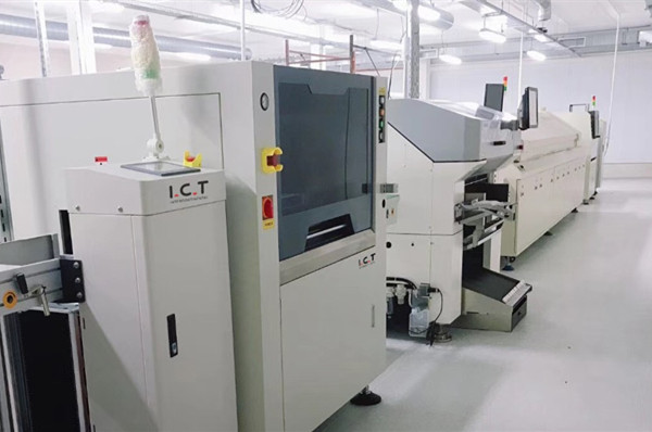
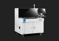
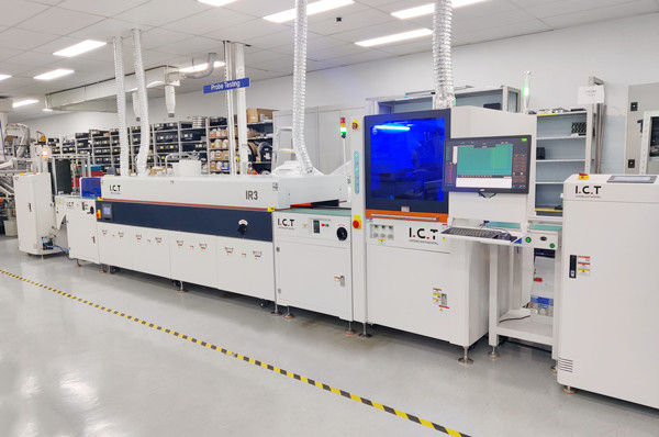
Station 3 is squeegee — the headline number on every printer brochure, the only station that an architect will quote without being asked, and the source of more throughput calculation errors than any other. The four sub-questions below cover the relationship between print stroke length and board length (and why a 1.05× rule protects paste rheology without taxing takt), the pressure ramp and dwell that turns a clean stroke into a wet one, the squeegee-speed ceiling that the paste rheology and the surface finish enforce, and how this station maps onto the I.C.T stencil printer configuration options that an integrator actually specifies. The figure accompanying this section shows the operator view of a squeegee stroke on a real printer — the kind of photograph where the geometry of the head, the stencil frame, the printed board and the operator's hand are all visible in one frame, which is the right level of detail for a process engineer to read the cycle.
Squeegee is the station where most of the throughput improvement during the last ten years has happened. Servo-driven squeegee heads have replaced pneumatic ones; closed-loop pressure control has replaced spring-set pressure; the squeegee speed profile (accelerate-cruise-decelerate) is now software-defined rather than mechanically clamped. Those three changes have roughly halved the per-stroke time of a mid-class printer compared to the pneumatic-and-spring generation, but the speed has not been added back into the cycle naively — the dwell, the separator timing and the print-direction reversal are still governed by the same rheology of the solder paste, and a printer that tries to squeegee faster than the paste allows will fail in solder-ball rate, not in takt. The art is to find the speed ceiling, not to ignore it.

The print stroke length is the distance the squeegee head has to travel to cover the print area of the board, plus a small overlap on each end to push excess paste off the aperture area and into the recovery zone. The naive rule is "stroke length = print direction length of the board". The better rule, adopted by every printer we integrate as a working discipline, is "stroke length = 1.05 to 1.10 × print direction length", with the longer end of the range used when the print starts or ends near a BGA or a connector pin field that the stencil designer has marked as a paste-volume-sensitive area. The 1.05× rule costs roughly 5 % more stroke length than the naive rule and protects print quality on the most paste-volume-sensitive 10 to 20 % of boards in the line.
The impact on takt is small (5 % more stroke length at the same speed is 5 % more stroke time, on top of a station that is already 3.0 to 4.5 s of the cycle), and it is the right cost to accept. The error in the opposite direction — cutting the stroke short to save time — costs solder-bead defects downstream and SPI rejects. In throughput terms, an SPI reject of one board per hundred is roughly equivalent to losing 1 % of throughput; a bead-defect recovery (rework, retouch, or scrap) costs one operator's full attention per shift. Read 1.05× as the floor, 1.10× as the reasonable upper bound, and never go below 1.0× — that single rule saves more yield arguments than any other line-design decision on the printer.
Squeegee pressure is the second of the two controllable inputs into station 3, and it has been over-thought for years. The traditional approach was to set a high pressure to force paste through the apertures and accept that a thin board would bow; the modern closed-loop approach is to set a low base pressure (0.3 to 0.8 kg/cm of squeegee length for most lead-free pastes) and add a controlled dwell at the end of the stroke. The dwell is a small additional pressure that holds the squeegee against the stencil for 0.05 to 0.20 s after the head has reached the end of its motion; it pushes a final increment of paste through the apertures on the trailing edge of the print area.
The dwell is misunderstood on most lines, because the intuitive assumption is "more dwell = better paste transfer", and the empirical reality is that dwell helps up to a point and then it begins to leak paste around the squeegee and onto the stencil top side. A dwell of 0.10 to 0.15 s is the sweet spot for most Type 4 lead-free pastes at 30 to 100 mm/s squeegee speed; above 0.20 s the aperture fill stops improving and the stencil begins to clog at the edges. The cycle-time cost of a longer dwell is roughly equal to the dwell time itself, so doubling the dwell from 0.10 s to 0.20 s adds 0.10 s to every cycle. On a 7 s cycle that is a 1.4 % throughput tax, which is the right cost for the yield protection it gives on small-aperture boards. On large boards that have no small apertures, the engineer should be willing to lower the dwell back to 0.05 s and recover the cycle time.
Squeegee speed is the input that every brochure wants to maximise and that paste rheology actually limits. Lead-free Type 4 pastes — the workhorse of mid-class production lines — print cleanly at 20 to 80 mm/s on a stainless-steel stencil with a fine-grain finish. Type 5 pastes (smaller powder, more printing pressure required) print cleanly at 15 to 50 mm/s. Type 6 and Type 7 pastes (used for 008004 and 01005 components on premium lines) print cleanly at 10 to 30 mm/s. Each step down in particle size costs roughly half the maximum squeegee speed, which translates to twice the per-stroke time on the same board.
There is therefore a "printable throughput ceiling" for every combination of paste and component density, and the ceiling is lower than most engineers assume. A line printing 008004 components on a Type 6 paste at 15 mm/s on a 200 mm print direction will spend 13.3 s in the squeegee stroke alone, before any of the other stations is added — and that 13.3 s is already a higher cycle than the brochure headline number on most mid-class printers, so the line will run at whatever 1.0 to 1.5× of 13.3 s the slowest station enforces. The lesson is to read the squeegee speed spec as a maximum value, not as a planning value, and to size the line on the speed the customer's actual paste will print at.
The relationship between squeegee geometry, paste rheology and the printer's mechanical design is the place where the choice of machine class starts to matter in throughput terms. Two configurations of fully automatic stencil printer in the I.C.T range are worth comparing here, because they sit at opposite ends of the squeegee performance envelope. The I.C.T P6 semi-automatic solder paste printer is the canonical mid-class semi-automatic stencil printer: hand-loaded boards, hand-cleaned stencil, single-axis servos, a 50 to 100 mm/s squeegee speed envelope, and a 6 to 9 s cycle time on a 300 × 200 mm board with two-fiducial alignment. The P6 has a published CPH in the 240 to 320 range when a single operator is loading boards at top speed, and the operator's foot-and-hand time defines the takt more than the printer's mechanics. The economics of the P6 are excellent for prototype and low-volume lines precisely because the operator's pace is the slowest station, not the machine's.
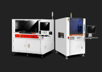
At the top of the range, the I.C.T 6534 SMT solder paste printing machine is the canonical high-throughput fully automatic stencil printer: inline magazine loader, auto-width conveyor, dual-direction squeegee head with independent pressure control, two-vision system, automated under-stencil cleaning with both wet paper and vacuum wipe, and a 4 to 6 s cycle time on the same 300 × 200 mm board. The 6534's published CPH is in the 550 to 650 range, and the slowest station on a clean recipe is the squeegee stroke itself — there is no operator in the cycle. The two printers illustrate the central point of this section: the squeegee station is the headline, but the offline stations (load, vision, clean) are the throughput ceiling, and the gap between a P6 and a 6534 is mostly in those three stations, not in the squeegee. Engineers should size the machine class to the operator model and the recipe complexity, not to the squeegee speed alone.
Station 4 is stencil release, and it is the most underappreciated station on the printer. The mechanism is simple — the Z axis lifts the stencil 0 to 2 mm off the board, holds that gap for 0.0 to 0.3 s, and physically separates the stencil from the solder-paste deposits. The reason it matters for takt is that the snap-off dwell time is a hard floor on how fast the next station can begin, and that dwell time is determined by the rheology of the paste, the surface finish of the stencil, and the under-stencil vacuum (or its absence). The three sub-questions below cover the snap-off distance and dwell trade, the stencil aperture finish and the defect-frequency curve, and the vacuum under-stencil function that turns a slow release into a fast one.
The single most common throughput error in this station is to assume that the snap-off happens "instantly" because it is governed by a 0.2 mm motion that takes the Z axis under 0.1 s to complete. The motion does happen that fast; what does not happen that fast is the paste releasing from the apertures. A paste deposit on a small aperture has to overcome its own adhesion to the aperture wall, and the time it takes to release is the dwell time — anything from 0.05 s on a forgiving Type 4 paste to 0.30 s on a Type 6 paste with high surface tension on a rough aperture. The dwell is a tax on every cycle, and engineers who skip it in their takt model always over-rate throughput by 5 to 10 %.
Snap-off distance is the vertical gap between the bottom of the stencil and the top of the board at the moment of separation. The distance itself has almost no time cost — most Z axes traverse the 0.5 to 2.0 mm range in 0.05 to 0.20 s — but the dwell at that distance is the variable that determines whether the cycle is on the verge of solder-ball defects or not. The empirical rule from a decade of integration work is that the dwell-after-print should be in the 0.05 to 0.20 s range for the vast majority of production lines; below 0.05 s the paste does not have time to release from small apertures, and above 0.30 s the printer is paying for dwell time it does not need.
The width of that dwell window is determined by the paste, the aperture finish and the under-stencil support. Lead-free Type 4 pastes with 20 to 30 µm powder size print cleanly at 0.10 s dwell on most apertures; a line running 008004 components on Type 6 may need 0.20 s; a line running 0.5 mm pitch QFPs on Type 3 may need only 0.05 s. The cycle-time saving from a tighter dwell is roughly equal to the dwell reduction: tightening a recipe from 0.20 s to 0.10 s saves 0.10 s per cycle, or roughly 1.5 % on a 7 s cycle. The yield saving from a longer dwell is visible directly in the SPI's solder-ball rate, and it shows up again in the placement machine's tombstone rate. The right commissioning rule is to start at 0.15 s and tighten by 0.05 s only if the SPI sees no paste artefacts over a full panel run.
The stencil aperture finish is the single largest variable in the snap-off station. Electro-polished stainless steel apertures have the lowest surface roughness (~0.05 to 0.10 µm Ra) and the cleanest paste release; laser-cut apertures have a higher surface roughness (~0.30 to 0.60 µm Ra) and a more variable release time, which the dwell has to absorb. Nano-coating (a polymer or DLC coating applied to the aperture wall) cuts the release variability roughly in half, but the coating wears off over 30,000 to 80,000 print cycles, which is why nano-coated stencils become progressively slower (and eventually defect-prone) in the last third of their life.
The relation between aperture finish and required dwell forms a curve engineers should be able to draw from memory. At the clean end: electro-polished, nano-coated, Type 4 paste, 0.05 s dwell. At the dirty end: laser-cut, uncoated, Type 6 paste, 0.30 s dwell. The cycle-time cost across that range is roughly 0.25 s per cycle, which is 3 to 4 % of a 7 s cycle. On a premium line printing 008004 components, the engineer should be willing to spend $1,500 to $3,000 on a nano-coated electro-polished stencil to recover 0.20 s per cycle of dwell — the payback at the line's own throughput rate is roughly three to six months. On a prototype line printing only 0.5 mm pitch QFPs, the dwell saving is small enough that a standard laser-cut stencil is fine, and the spend is not justified.
Vacuum under-stencil is a feature that turns a slow release into a fast one in the worst-case board of the line. The mechanism is a vacuum plenum inside the support table below the board; when activated, it pulls air through small holes in the support plate, drawing the board flat against the support pins and creating a small pressure differential at every aperture that helps the paste release. On a thin board (0.4 to 0.8 mm) the vacuum is what stops the board from lifting off the support pins during the snap-off motion and creating solder beads on the underside; on a thick board (1.6 mm+) the vacuum is less important because the board has enough stiffness to stay flat on its own.
The cycle-time cost of the vacuum is small (0.05 to 0.15 s of vacuum pump-down on every cycle) and the yield benefit is large. On a 1.6 mm board, the vacuum is optional and the engineer can disable it on most recipes; on a 0.8 mm board, the vacuum is mandatory and disabling it creates the well-known "tombstone after reflow" failure mode that is hard to diagnose from the SPI alone. The right commissioning rule is to enable the vacuum by default on every recipe, and accept the 0.05 to 0.15 s tax as a permanent insurance policy for unknown boards that the line may pick up in the next two years.
The last detail in station 4 is the underside wipe, which is the small dry or wet wipe that the printer runs across the underside of the stencil between every cycle or every N cycles. The wipe is typically a roll of dry paper that advances a fixed amount each cycle, indexed automatically by the printer; on premium machines it is a wet paper with a solvent dispense nozzle. The cycle-time cost depends entirely on whether the wipe is run on every cycle or only every Nth cycle: an every-cycle wipe on a 250 mm stencil typically adds 0.3 to 0.5 s to the cycle; an every-fifth-cycle wipe on the same stencil adds only 0.06 to 0.10 s per cycle on average.
Pre-wipe stencils — stencils that have been coated with a release-agent before installation — change the trade-off in a useful way. A nano-coated stencil runs cleanly for 8 to 20 cycles between wipes, depending on the paste and the surface finish; a standard laser-cut stencil runs cleanly for 2 to 6 cycles between wipes. On a high-end line printing 0.5 mm pitch QFPs on a nano-coated stencil, an every-eighth-cycle wipe gives a per-cycle tax of 0.04 to 0.06 s and prints defect-free. On a prototype line printing leaded solder on a standard stencil, an every-third-cycle wipe gives a per-cycle tax of 0.10 to 0.17 s and prints clean solder balls. The two configurations together produce per-cycle taxes that vary by roughly 10×, and the engineer who picks the wrong combination will either over-clean the stencil (and pay the cycle time) or under-clean it (and pay the SPI rejects).
Station 5 is cleaning, and it is the station that turns a "7 s cycle" printer into a "10 s cycle" printer on most real shifts. The mechanism is the under-stencil wipe (or vacuum cleaning) that runs after a configurable number of cycles to keep solder-paste residue from accumulating on the stencil underside; the wipe cycle is typically a sequence of wet, dry and vacuum steps that takes 1.5 to 4.0 s end-to-end. Two non-obvious facts make this station expensive. First, the wipe cycle is invisible on every CPH brochure because the brochure assumes an "every-N-boards" wipe that does not run on every cycle; second, the actual wipe frequency required to keep the stencil clean is determined by the paste, the aperture finish and the through-put rate, and a printer set to wipe every 8 boards on a paste that needs every 5 boards will start to print contaminated apertures within a shift.
The four sub-questions below cover the wet/dry/vacuum wipe sequence and the per-cycle budget, the clean-every-N configuration options, the solvent and consumable budget that the cleaning station consumes (which is itself a takt input because the paper has to be reloaded), and the way this station is linked back to the I.C.T stencil cleaning machine as an offline service. The figure accompanying this section shows the technician's view of the stencil release — the same kind of stencil-rotation shot used in Figure 2, but at the moment the stencil is being lifted off a freshly-printed board and the cleaning station is moving into position.

Modern stencil cleaning stations on premium printers run a three-step sequence: wet wipe (a paper roll that has been moistened with a solvent, typically a low-VOC alcohol or a specialist cleaning fluid), dry wipe (a dry paper roll that absorbs residual solvent), and vacuum wipe (a vacuum nozzle that pulls loose paste residue off the stencil underside and out of the apertures). The whole sequence takes 1.5 to 4.0 s on a 250 to 400 mm stencil, depending on the wipe length, the vacuum pump capacity, and the number of stroke passes. The wipe is typically configurable in two directions (forward only, or forward and reverse) and two speeds (high-speed single-pass, or low-speed double-pass).
The per-cycle budget for cleaning depends on the configured frequency. At every cycle, the budget consumes 1.5 to 4.0 s and the printer runs at the speed of the wipe. At every fifth cycle, the budget is amortised to 0.3 to 0.8 s per cycle; at every tenth cycle it is amortised to 0.15 to 0.4 s per cycle. Engineers estimating throughput should always express the wipe as "amortised per cycle" rather than "per wipe event" because the brochure and the operator's experience live in different units. The table below shows the amortised wipe budget for the four most common configurations on a mid-class 6534-class printer running lead-free Type 4 paste.
Wipe mode | Wipe duration (single event) | Frequency configured on line | Amortised per-cycle tax | Typical paste residue outcome |
|---|---|---|---|---|
Wet-only single-pass | 1.5 s | Every 5 boards | 0.30 s | Slight residue at high humidity; SPI solder-ball rate stable |
Wet + dry single-pass | 2.5 s | Every 5 boards | 0.50 s | Clean underside; SPI solder-ball rate flat across shift |
Wet + dry + vacuum single-pass | 3.2 s | Every 5 boards | 0.64 s | Cleanest; needed on Type 5/6 lines or on 008004 components |
Wet + dry + vacuum double-pass | 4.0 s | Every 8 boards | 0.50 s | Cleanest at the lowest per-cycle tax; the configuration most often seen on high-end lines |
The most common error in this station is to set the wipe to "every 10 boards" because it looks like a takt-saving. In practice a wet-only every-10 single-pass budget builds up residue on the stencil underside and forces the SPI to alarm on every 200th board or so, at which point the operator has to stop the line and run a manual clean — a 60 to 180 second penalty that overwhelms any amortised saving. Set the wipe frequency to the shortest interval the paste will print cleanly through, then run a 30-minute SPI log to verify that the residue is not building up.
The wipe frequency is the single most-tunable input into the cleaning station, and it is set on a per-paste basis rather than a per-printer basis. The general rule is that as the powder size shrinks (Type 4 → 5 → 6) and as the component density rises (0.5 mm QFP → 0.4 mm QFP → 008004), the wipe frequency has to shorten. A Type 4 paste on a 0.5 mm pitch QFP line will print cleanly on an every-8 to every-20 wet-only wipe; a Type 5 paste on a 0.4 mm pitch QFP line needs an every-5 wet + dry wipe; a Type 6 paste on an 008004 line needs an every-3 or every-5 wet + dry + vacuum double-pass wipe. The cost of moving from an every-8 to an every-5 wipe is roughly 0.35 s of amortised cleaning tax per cycle, or roughly 5 % of a 7 s cycle.
Two practical lessons follow. First, the wipe frequency should be tuned by recipe, not by line — the same printer on the same shop floor will run an every-12 wipe for the easy recipes and an every-5 wipe for the dense-component recipes. Second, the wipe frequency should be driven by SPI data, not by operator intuition: a 30-minute SPI log will show the residue pattern (paste volume drop, paste area variance, x/y offset drift) at the end of each configured interval, and the engineer can pick the longest interval that the SPI data allows. Engineers who set the frequency based on "how clean the stencil looks at the end of the shift" are tuning by visual inspection rather than by SPI data, and will almost always under-clean the dense-component recipes.
Cleaning is also where the consumable budget lives, and the consumable budget has a takt input that the brochure never mentions. A wet wipe consumes roughly 0.5 to 1.5 mL of solvent per wipe event; an every-five-boards wipe on an 8-hour shift consumes roughly 1 to 3 L of solvent. A dry paper roll on a 250 mm stencil consumes roughly 0.5 m of paper per cycle; an every-eight-boards double-pass wipe on an 8-hour shift consumes roughly 300 m of paper (one roll). Both consumables have to be reloaded by the operator — solvent reservoir refill takes 30 to 60 seconds every shift, paper roll change takes 15 to 30 seconds every two to four shifts. Both reload events stop the line, and the operator's reload time is on top of the cycle-time budget for the cleaning station.
The operator reload time converts to a throughput tax in the most direct way. An 8-hour shift at 100 % utilisation with a mid-class printer runs roughly 4,000 to 5,000 boards; a 30-second solvent refill adds roughly 5 boards of throughput loss; a 20-second paper change every four shifts adds roughly 1 board of throughput loss. These are small per-shift numbers, but they show up repeatedly as the solvent and paper are the inputs the line manager forgets to budget for when he or she sets the operating cost target. The right place to record them is on the recipe header sheet, alongside the paste batch ID and the stencil serial number, and the right place to monitor them is on a weekly consumables review with the line supervisor.
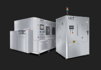
On lines that run the printer at very high utilisation (above 90 % time-on-line), or on lines that run a sticky paste that the inline cleaning station does not handle well, an offline stencil cleaning machine can take the cleaning station off the printer's critical path entirely. The offline machine is a stand-alone stencil-cleaning bench that the operator runs the stencil through once per shift or once per recipe change; the cleaning cycle runs while the printer continues to print with a back-up stencil. The benefit is that the inline cleaning station on the printer can be turned down to "every-20" frequency (or to "no inline wipe"), and the slow offline wipe no longer sits on the critical path of every cycle.
The trade-off is the second stencil itself. A capital stencil costs $400 to $1,500 in raw material plus nano-coating, and the second-stencil flow requires a process to swap the stencil in and out without damaging it (most lines use a stencil storage rack and a single-operator swap procedure that takes 3 to 5 minutes). On a high-end line running three shifts, the savings from the offline cleaning machine typically pay for the second stencil in three to six months; on a single-shift prototype line, the savings never pay for the stencil. Engineers should size the cleaning strategy on the line's utilisation, not on the printer's brochure — the answer is different for high-end mass production than it is for prototype.
Station 6 is board exit, and it is the second of the two stations that engineers routinely underestimate. The mechanism is the out-feed conveyor releasing the printed board, the next machine in the line (or an NG reject chute) accepting the board, and the printer confirming the slot is empty before the next cycle begins. The three sub-questions below cover the out-feed geometry and the magazine receiver, the NG-versus-good board buffer pattern that premium printers offer, and the inline hand-off to the next machine in line (an SPI or a pick-and-place) and the "next-takt coupling" that determines whether the two stations run at the printer's speed or the line's slowest station's speed.
This station matters disproportionately for line integration because it is where the printer meets the rest of the SMT line, and the line's overall throughput is only as good as the slowest hand-off. A printer that exits a board every 7.0 s is not running at 7.0 s if the SPI cannot inspect a board every 7.0 s; the line takt will rise to 9 or 10 s to match the SPI, and the printer's capacity goes to waste. The three sub-questions below show how to size the exit station so the printer's capacity is delivered to the line, and how to choose among NG buffer, good-board buffer and inline SMEMA-style hand-off to keep the takt of the printer aligned with the takt of the line.

The out-feed conveyor of a stencil printer is the silent partner of the in-feed conveyor, and the two have to be designed together. A typical inline printer ships with an out-feed length of 300 to 600 mm, a magazine receiver on the downstream end that holds 30 to 50 boards, and an NG reject chute on the side of the conveyor that physically diverts bad boards out of the line. The cycle-time cost of the out-feed is small (the conveyor's exit roll typically takes 0.1 to 0.3 s to advance and release), but the cycle-time cost of the magazine receiver is not small — a single-piece feed magazine on the exit can buffer 10 to 30 boards of NG or good boards, and the receiver has to empty before the printer's cycle can close. On high-utilisation lines, the receiver becomes a takt input.
The NG reject path has its own cycle-time cost. When a board fails the in-line SPI check, the printer has to be notified of the failure, the conveyor has to advance the NG board to the reject position, and the reject cylinder has to fire and push the board sideways into the chute. The whole reject sequence on a mid-class printer takes 0.6 to 1.5 s, which is roughly two to four times the normal exit cycle. The SPI reject rate therefore has a disproportionately large effect on the line takt — a 1 % SPI reject rate on a line that prints 500 boards per hour means 5 rejects per hour, each costing roughly 1 second of takt loss on average. The right place to monitor SPI reject rate is on the line's daily KPI sheet, alongside the printer's own cycle-time log.
The choice between an NG buffer, a good-board buffer, and no buffer at the exit of the printer is a layout decision with a takt consequence. An NG buffer holds the rejected boards physically aside from the main flow, so the main flow never has to stop; a good-board buffer holds accepted boards in a queue so the line can keep moving through SPI glares or pick-and-place slowdowns; no buffer (the default on cheaper printers) stops the conveyor the moment an SPI reject lands. The takt impact of these three options varies from 0.2 to 0.6 s on average for the whole line. An NG buffer saves roughly 0.2 to 0.4 s on average per board because the conveyor can release the next good board while the rejected board is being pushed aside. A good-board buffer saves 0.3 to 0.6 s on average per SPI reject, but only if the buffer is large enough to absorb the reject back-pressure.
The trade-off is mechanical cost and footprint. An NG buffer is a small chute on the side of the conveyor with no mechanical arm; the takt saving is small but the cost is small. A good-board buffer is a multi-slot vertical rack on the conveyor that requires its own motion controller; the takt saving is real but the capital cost is several thousand dollars and the footprint roughly doubles. Engineers should not spec a good-board buffer unless the SPI reject rate is consistently above 1 %; below that rate the ROI is negative. An NG buffer should be standard on every line with an SPI, because the capital cost is negligible and the takt saving compounds over the line's operating life.
The last detail in the out-feed station is the inline link to the next machine in the line, and it is the most common cause of a printer's headline capacity not being realised on a real line. The link can be SMEMA (Surface Mount Equipment Manufacturers Association) cable signalling, a Hermes standard, or a proprietary printer-to-machine handshake; the language can differ but the meaning is the same: the printer tells the next machine "board is at the exit, please accept"; the next machine tells the printer "I am not ready, please hold"; and the printer's exit conveyor waits if the next machine is not yet ready. The cycle-time cost of a wait event is roughly 0.5 to 1.5 s on average per event, and the frequency of wait events is set by the next machine's slowest station.
The right way to avoid the "next-takt coupling" tax is to either size the next machine to be faster than the printer, or to install a buffer between the printer and the next machine that absorbs the wait events. The first option is expensive and only works when the next machine is the SPI (which is typically faster than the printer). The second option is the right one for the printer-to-pick-and-place link, because the pick-and-place machine is almost always slower than the printer, and the buffer has to be sized to absorb pick-and-place slowdowns. The buffer size is roughly the same as the pick-and-place machine's "slowest cycle" minus the printer's cycle, expressed in boards; for a printer running 7 s and a pick-and-place running 9 s, a 5 to 10 board buffer is enough.
The previous seven sections have walked through the six stations one at a time and shown what each one costs. The four sub-questions in this final section assemble the costs into a single throughput number, compare six real-world printer configurations on a fixed example, walk through the most common throughput traps we see in industry audits, and present the worked formula that an integrator or a line manager can use to build a takt budget before committing to a printer class. The central output of section 8 is the realistic solder paste printer cycle time and throughput budget that survives the first 30 days of a new line. The reference configuration table below covers the six printer classes in the I.C.T range that this article has referenced in earlier sections, and it gives the realistic per-cycle time, the realistic CPH on a single shift, and the assumption about operator presence that drove each CPH figure.
The single most important number in this section is "realistic CPH". Realistic CPH is the number an engineer should put on a customer's quote, on a line capacity review, or on a takt budget; it is the number that survives the first 30 days of a new line. Realistic CPH is roughly 55 % to 65 % of the brochure CPH on a mid-class line and roughly 65 % to 75 % of the brochure CPH on a high-end line. The table below applies the 60 % median ratio to the mid-class configurations and the 70 % ratio to the high-end ones, and it gives the six most-used printer classes in the I.C.T range with the envelopes they actually deliver on a 300 × 200 mm board with two-fiducial alignment and a mid-volume lead-free paste.
Printer class | I.C.T model | SPT brochure | Realistic cycle (300×200 mm) | Realistic CPH | Operator presence |
|---|---|---|---|---|---|
Semi-automatic, single fiducial | 6 s SPT | 11–14 s | 260–325 | Always present (board load + stencil wipe) | |
Fully automatic entry, two fiducials | 7 s SPT | 10–13 s | 280–360 | Periodic (paste, stencil swap, recipe change) | |
Fully automatic mid-range, two-three fiducials | I.C.T 5151 solder paste PCB SMT screen printer (reference class) | 8 s SPT | 11–14 s | 260–325 | Periodic (recipe, paste, NG buffer) |
Fully automatic high-end, dual-direction squeegee | I.C.T 5134 online fully automatic solder paste printer (reference class) | 6 s SPT | 9–12 s | 300–400 | Periodic (recipe change and paste) |
Long-board fully automatic, dual squeegee | I.C.T 1500 long-board fully automatic LED PCB stencil printer | 10 s SPT | 14–18 s | 200–260 | Periodic (long-board handling) |
Selection guide, buying checklist and FAT/SAT references for this article | This article cites these three peer articles in the cross-references: Automatic vs Semi-Automatic stencil printers, Buying Checklist, FAT and SAT Checklist | — | — | — | — |
The reference configuration table covers the six printers in the I.C.T range that an integrator or a line manager would consider for a 2026 production line, plus the four peer articles in the I.C.T library that an engineer can read for the deeper dive on each axis (selection, automatic-versus-semi-automatic, buying checklist and FAT-SAT checklist). The six rows of printers are organised from cheapest (P6 semi-automatic) to most expensive (1500 long-board), and the columns give the brochure SPT (the headline spec the vendor publishes), the realistic cycle time on a 300 × 200 mm board with two fiducials and a mid-volume lead-free paste, and the realistic CPH that the line will see on a single 8-hour shift at 100 % time-on-line. The operator-presence column tells the engineer what kind of operator attention the printer requires — periodic versus continuous — because that is the most under-budged line item in most takt reviews.
The numbers in the table are working values from our integration team's most recent cycle-time studies; they are roughly 60 to 70 % of the brochure values, with the higher end of the buffer for the high-end machines. Engineers should treat the lower end of the CPH range as the planning number for a quote (which is when the customer wants the most pessimistic number to be conservative), and the upper end as the planning number for a takt budget after the line has been running for 30 days (when the line's real pattern of recipe changes, paste replenishments and SPI rejects is known). The 1500 long-board line carries a larger overhead because long boards take longer to load and to traverse the squeegee stroke; this is a feature, not a bug, because the alternative is to run two separate printing steps on the long board, which doubles the labour cost.
To make the table operational, two worked examples below show the conversion from realistic cycle time to line throughput in boards per hour, in boards per shift, and in boards per week. The first example assumes a mid-class fully automatic line (6534-class) running lead-free Type 4 paste with two-fiducial alignment, a wet + dry wipe every 5 boards, and a 300 × 200 mm board mix. The second assumes a high-end line (5134-class) running the same board mix but with nano-coated stencil, dual-direction squeegee head, and an every-8 wet + dry + vacuum wipe. Both examples include 12 SKU changes per 8-hour shift, a 30-second solvent refill at the half-shift mark, and a 0.7 % SPI reject rate — the values most often seen on real lines in our integration work in 2026.
Mid-class example, 6534 class: realistic cycle = 11.0 s on the clean recipe, plus an amortised 0.50 s for every-five wipe, plus 0.30 s of amortised solvent refill time, plus 0.6 s of amortised SKU changeover time on auto-width conveyor — total 12.4 s. CPH = 3600 / 12.4 = 290 boards per hour. Per 8-hour shift at 95 % time-on-line (5 % lost to breaks, changeover, paste replenishment) = 290 × 8 × 0.95 = 2,204 boards. Per 5-shift week = 11,020 boards. The line's "headline" brochure CPH for the 6534 is 514 (computed from the 7 s SPT); the gap between 514 and 290 is the 44 % throughput tax of stations 1, 2, 5, 6 and the offs-line overhead that every brochure ignores. The right budget number for a customer thinking about the 6534 is therefore 290 CPH, not 514 CPH.
High-end example, 5134 class: realistic cycle = 9.0 s on the clean recipe, plus amortised 0.40 s for every-eight wipe with vacuum, plus 0.20 s of amortised solvent refill time, plus 0.4 s of amortised SKU changeover time on auto-width conveyor — total 10.0 s. CPH = 3600 / 10.0 = 360 boards per hour. Per 8-hour shift at 95 % time-on-line = 360 × 8 × 0.95 = 2,736 boards. Per 5-shift week = 13,680 boards. The 5134's headline brochure CPH is 600; the realistic CPH is 360; the gap (40 %) is the right place to spend a few minutes of conversation with the customer to align the budget number. Engineers should always quote the realistic CPH, because a customer who plans on the brochure CPH will over-staff the line and under-build the capacity of the downstream pick-and-place.
The final piece of the assembly is the list of throughput traps that don't show up on spec sheets, but that we have seen cause 10 % to 25 % throughput losses on real lines in our integration work over the last decade. They are written here in the order in which they typically appear on a new line: (1) the recipe changeover tax being treated as amortised per-board instead of as a per-changeover event; (2) the paste replenishment cadence being treated as a one-off rather than as a recurring amortised tax; (3) the SPI reject rate being treated as a quality issue (off the printer's books) rather than as a printer takt input; (4) the solvent and paper consumables being treated as an operating cost line (rather than as a takt input); (5) the next-machine hand-off coupling being ignored until the line is already at 70 to 80 % utilisation and starts to back up. Each of these is a 5 to 15 minute fix at commissioning, and a 1 to 3 % throughput recovery per shift for the lifetime of the line.
The five traps share a single root cause — the printer brochure numbers are measured without any of the inputs in the table, and the integrator's job is to put those inputs back into the budget before the customer signs the order. The fix is mechanical: build the takt budget before the order is signed, ask the vendor for the slowest station's worst-case time, add the offline overhead as a per-cycle tax, and quote the customer the realistic CPH figure rather than the brochure figure. An integrator who does this for every line will save the customer roughly 15 to 20 % of throughput disappointment; an integrator who quotes the brochure will see a steady stream of order-amendment requests after the line has been running for 60 to 90 days. The reason this trap recurs on every new line is that the brochure number is the only number the buyer's procurement team can quote upward, and the realistic solder paste printer cycle time and throughput only emerges once the integrator has walked the six stations with a stopwatch on the customer's floor.
The worked throughput budget formula for a new line is: realistic CPH = 3600 / (cycle time + amortised cleaning tax + amortised overhead tax), where the cycle time is the per-station sum from Section 1.1, the cleaning tax is the amortised wipe time per cycle, and the overhead tax is the sum of all other amortised per-cycle overheads (paste replenishment, recipe change, SPI reject, NG divert, hand-off wait, operator reload). The formula gives a single number per printer-per-recipe, and an integrator can compute it in roughly fifteen minutes by walking the customer through the seven stations above with a stopwatch and the recipe header sheet. The recipe header sheet is the right place to record the number, because the recipe header sheet is also the place the line manager will look when a takt regression appears six months later.
A full worked example on a 6534-class line printing a 250 × 200 mm board with three fiducials, Type 5 paste, every-five wet + dry + vacuum wipe, 12 SKU changes per shift and 0.8 % SPI reject rate: station 1 board-in 0.8 s, station 2 three-fiducial alignment 1.4 s, station 3 squeegee stroke (50 mm/s on Type 5, 200 mm print direction with 1.05×) = 4.2 s, station 4 snap-off 0.3 s, station 5 amortised cleaning 0.64 s, station 6 board-out + hand-off 0.5 s. Per-cycle overhead = 12 SKU changes per 4,500 cycles per shift = 0.04 s of amortised recipe time, plus 30 s solvent refill per 4,500 cycles = 0.007 s, plus 36 SPI rejects per 4,500 cycles = 0.05 s of amortised NG-divert time. Total: 0.8 + 1.4 + 4.2 + 0.3 + 0.64 + 0.5 + 0.04 + 0.007 + 0.05 = 7.94 s. Realistic CPH = 3600 / 7.94 = 453, or 391 per shift at 95 % time-on-line, or 11,720 per 5-shift week. Customers who quote the brochure 514 CPH and get the realistic 391 have a clear path back to the budget; customers who quote the brochure and end up at 250 CPH have a gap that requires a takt-intervention plan. Use this worked example as the calibration reference any time a vendor quotes a new solder paste printer cycle time and throughput figure that looks suspiciously close to the brochure number.
Talk to an I.C.T throughput engineer
If you are sizing a new SMT line and would like a second opinion on the realistic solder paste printer cycle time and throughput of a candidate printer configuration, send us your worst-case board dimensions, the densest package on it, the solder paste you plan to use and your target shift utilisation; we will come back to you with a worked throughput budget in the same format as section 8.4 above, a takt-recovery plan if the budget is below your internal target, and a printer configuration that hits the CPH you need. We also run one-day takt audits on existing lines that are missing their daily output target, where our engineer walks the customer floor with a stopwatch and produces a station-by-station breakdown that the line manager can act on.
The I.C.T line covers semi-automatic, fully automatic inline and long-board fully automatic stencil printers, plus the matching stencil cleaning machines, solder-paste inspection and post-print AOI stations. If you need the wider stencil printer family first, the I.C.T solder paste printer product hub lists every model with cycle-time and CPH data on a common 300 × 200 mm reference board; the SMT solder paste printer selection guide for production lines walks the dimensions in the order that drives the choice; the SMT solder paste printer buying checklist packs nine procurement-review items into 28 questions; and the SMT solder paste printer FAT and SAT checklist covers the procedures every new machine has to pass before it prints a real shift. Long-board applications should also look at the I.C.T 1500 long-board fully automatic LED PCB stencil printer configuration, which adds a 1200 mm print direction for the LED industry and a dual-direction squeegee head that halves the per-stroke time on long boards.
What to send: worst-case board dimensions, the densest package pitch, the solder paste type and brand, your target CPH and shift pattern. Reply is typically within one business day.
A modern fully automatic solder paste printer will hold a realistic cycle time of 7 to 13 seconds on a 300 × 200 mm reference board, depending on the number of fiducials, the squeegee speed the paste allows, the cleaning frequency, the board-handling options and whether the next machine in line is ready. Brochure numbers between 5 and 8 seconds are measured in factory-tuned fastest mode and exclude cleaning, paste replenishment and recipe change; the realistic cycle time on a real shift is roughly 40 to 65 % above the brochure. Engineers planning a new line should treat the lower end of this range as a planning number on a clean recipe and the upper end as a planning number on a real-shift recipe with operator presence, paste replenishment and 12 SKU changes per shift.
CPH means cycles (or boards) per hour; from a cycle time in seconds the formula is CPH = 3600 / cycle_time_seconds. The conversion requires the realistic cycle time, not the brochure number; an example: a 7-second brochure cycle on a 6534-class printer becomes 10 to 12 seconds when amortised cleaning, paste replenishment, recipe change and SPI reject overhead are added back in, giving a realistic 300 to 360 CPH. For multi-shift planning, multiply CPH by the number of shifts per day by 0.95 (assumed time-on-line). The full formula is in section 8.4 of this article, with a worked example that covers a 6534-class line and a 5134-class line on a common 250 × 200 mm board with three fiducials and Type 5 paste.
SPT (Stencil Printing Time) is the full board-to-board cycle time on a factory-tuned recipe, covering stations 1 to 6 minus cleaning; DPT (Direct Printing Time) is the squeegee stroke only, measured with the camera in skip mode and the paste already rolled. SPT is the brochure number; DPT is the number a brochure shows in a footnote or an application note. The difference between them is TA (Total Allocation), which is the auxiliary overhead: cleaning, paste roll-up, recipe recall, NG divert and short pauses. TA is the gap between the brochure number and the realistic cycle time, and it is what makes a 7-second SPT printer produce 200 to 380 boards per shift instead of the 514 CPH that the SPT number implies. Engineers comparing two printers should always ask for the same envelope in both numbers.
Fiducial alignment adds roughly 0.5 to 1.2 seconds for a two-fiducial recipe on a clean board, and roughly 0.8 to 2.0 seconds for a four-fiducial recipe. The per-fiducial lookup latency depends on the cleanliness of the camera lens, the under-board illumination and the surface finish of the fiducial mark itself; clean dedicated fiducials in good conditions can lock in 0.15 to 0.20 seconds, while textured or partially-occluded fiducials can take 0.35 to 0.50 seconds. The position of the alignment station on the critical path makes its time cost roughly equal to its wall-clock cost on the cycle, which is why recipe changes that add a third or fourth fiducial show up directly in the throughput line of the daily KPI. Engineers should not add fiducials defensively — every added fiducial should be justified by a specific package on the board.
Squeegee speed should be tuned by recipe, not by line, because the printable speed ceiling depends on the solder paste type and the aperture density of the board. Lead-free Type 4 paste prints cleanly at 20 to 80 mm/s on a stainless-steel stencil with a fine-grain finish; Type 5 paste at 15 to 50 mm/s; Type 6 paste at 10 to 30 mm/s. A line that runs a stable mix of 0.5 mm pitch QFPs on Type 4 can run at 80 mm/s; the same line printing 008004 components on Type 6 has to drop to 25 mm/s, roughly tripling the squeegee stroke time. Set the squeegee speed per recipe at the highest speed that the SPI shows no paste-fill variance, paste volume drop or aperture residue over a thirty-minute sample run, and resist the temptation to push the speed past that ceiling for marginal throughput gain.
The stencil should be wiped at the longest interval that the SPI data still shows clean apertures, paste fill consistency and x/y offset stability. The interval depends on the paste, the aperture finish and the through-put rate: Type 4 paste on a nano-coated stencil will print cleanly on an every-eight to every-twenty wet-only wipe; Type 5 paste on a standard laser-cut stencil needs an every-five wet plus dry wipe; Type 6 paste on an 008004-component line needs an every-three or every-five wet plus dry plus vacuum double-pass wipe. A wet-only single-pass wipe takes about 1.5 seconds on a 250 mm stencil, amortised per cycle that is roughly 0.30 seconds at every-five boards, 0.15 seconds at every-ten and 0.04 seconds at every-twenty. Engineers should drive the wipe frequency from a thirty-minute SPI log rather than from operator intuition.
A longer board reduces printer throughput directly because the squeegee stroke length scales with the print direction length, and because the conveyor has to traverse more distance for the board-in and board-out stations. A 200 mm print direction at 50 mm/s on Type 5 paste takes about 4.2 seconds end-to-end with the 1.05× rule; a 400 mm print direction on the same paste at the same speed takes about 8.4 seconds, doubling the per-stroke time. Long-board applications therefore pick a printer class with a longer print direction (the I.C.T 1500 long-board fully automatic LED PCB stencil printer is a 1200 mm class machine) or they run two adjacent printing steps with a smaller-area stencil, which doubles the labour cost but keeps the squeegee stroke short. The right answer depends on volume: a single long-board shift on the 1500 is cheaper than two short-board shifts on the 6534 once the volume is above roughly 1,500 boards per shift.
The cheapest route to higher line throughput is to tighten the slowest station on the existing line, not to buy a faster printer. In practice the highest-return stations are: cleaning (move from an every-five to an every-eight wipe if the SPI still shows clean apertures, saving roughly 0.10 s per cycle, or 1.4 %); alignment (drop the recipe from four fiducials back to three or two if the worst board still has enough signal to print cleanly, saving 0.20 to 0.50 s per cycle, or 3 to 7 %); recipe-change overhead (move from a hand-crank conveyor to an auto-width conveyor if the line runs more than four SKUs per shift, saving roughly 8 seconds per changeover, or 1 to 2 % on a high-mix line); and the NG buffer (install an NG reject chute if the line doesn't already have one, saving 0.2 to 0.4 seconds per board on average). The combined gain from those four small changes is typically 5 to 12 % of throughput, recovered in a commissioning afternoon, without spending a single dollar on a new printer.