English
Views: 0 Author: Elsa Long Publish Time: 2026-10-29 Origin: Site


Feeder and nozzle selection is the least glamorous part of SMT planning and the part that quietly decides whether a placement machine runs at its quoted speed or stalls on a hundred small pick errors a shift. A Hanwha pick and place machine does not place components; it places what the feeder has presented and the nozzle has picked, so every reel, tray, tube and nozzle is a physical interface between a component and the machine, and a mismatch at either end shows up as a mispick, a tombstone, a dropped part or a defect that nobody can trace. This guide is a practical method for Hanwha pick and place feeder and nozzle selection, starting from the bill of materials and working outward through packaging form, component size, tape and tray logistics, and component risk, so that the feeders and nozzles you specify actually match the boards you build. The hardware context is the Hanwha SMT pick and place machine range, but the method applies to any Hanwha feeder platform.
The guide is organised around the order in which the decisions actually get made in a real project. It begins with why feeders and nozzles matter more than buyers expect, then shows how to read a BOM so component data becomes feeder and nozzle requirements instead of guesswork. It maps each packaging form — tape and reel, tray, stick, bulk — to the feeder class that can present it, then matches component size and package family to the right nozzle bore and tip. It covers the logistics of tape width, reel diameter and tray matrix, the risk controls that catch a wrong reel or a worn nozzle before it reaches the board, and finishes with a verification checklist that ties the whole selection together. Throughout, the aim is a feeder and nozzle set that is complete for the product list, repeatable across changeovers, and cheap to keep running rather than merely impressive on a quotation.
Table of Contents
A placement machine is often described by its head count, its CPH and its accuracy, and those numbers do matter, but they describe a machine placing ideal components from an ideal feeder with an ideal nozzle. Real production is less forgiving. The component arrives at the pickup point inside a pocket on a tape, or in a tray cell, or loose in a tube, and the feeder has to present it at exactly the right position, height and orientation for the nozzle to descend, seat, lift and carry it to the board. Every one of those steps is an interface, and the two interfaces that touch the component — the feeder below it and the nozzle above it — set the practical ceiling on yield and speed far more than the head's specification does.
This chapter explains why that is true and why the selection of feeders and nozzles belongs at the start of a project rather than at the end. It looks at the feeder as the component's first interface and the nozzle as its last, traces how small mismatches at either end turn into visible defects, and makes the case that Hanwha pick and place feeder and nozzle selection is a planning discipline, not an afterthought once the machine is installed. Understanding the two interfaces is what lets the rest of this guide move from principle to a concrete bill of feeders and nozzles.
The feeder is where the component meets the machine, and its job is deceptively simple: index the tape, tray or tube by one pitch so the next component sits in the pickup window at the right height and orientation, every time, for thousands of cycles. A tape feeder pulls the carrier tape forward by a precise pitch, peels back the cover tape, and holds the pocket steady while the nozzle descends. A tray feeder moves a matrix of pockets into position. A stick feeder tilts a tube so parts slide to the pickup end. In each case the feeder's accuracy, repeatability and calibration determine whether the nozzle sees a component centred in its pocket or nudged to one side.
The consequences of a feeder that is slightly off are not dramatic at first. A component a fraction of a millimetre low causes the nozzle to seat imperfectly; a tape that indexes short leaves the part half under the cover tape; a pocket that has stretched from wear lets the part rattle. Each of these produces a pickup error that the machine may or may not recover from, and the errors accumulate into a lower real CPH and a higher defect rate that is easy to blame on the head and hard to trace to the feeder. Good feeder selection starts from the component's real packaging and builds the presentation around it, because the feeder is not a peripheral — it is the first half of every placement.
If the feeder is the first interface, the nozzle is the last: it is the only part of the machine that actually touches the component, and it has to pick the part cleanly from the feeder, hold it through acceleration and travel, and release it accurately onto the pad. The nozzle's bore, tip geometry, material and spring behaviour all have to suit the component's size, mass and package. A nozzle too large for a 0402 chip will not seat reliably and will pick air or pick two parts; a nozzle too small for a large connector will not generate enough vacuum area to hold the part against acceleration; a worn tip loses its seal and drops parts intermittently.
Nozzle selection is therefore a matching problem, not a catalogue lookup. The same machine head can carry several nozzle types, and the program assigns a nozzle to each component based on its package and size. Getting that assignment right is what keeps pickup rate high and placement accurate, and getting it wrong produces the classic symptoms — mispicks, dropped parts, tombstoning on small chips, and skewed placement on larger parts. Because the nozzle is the final interface before the board, its condition and its match to the component are the last chance to get the placement right, which is why nozzle selection and nozzle wear management belong in the same conversation as feeder choice.
Feeder and nozzle problems rarely announce themselves as such. A worn feeder that indexes inconsistently shows up as a rising mispick count on one lane; a nozzle that has lost its tip seal shows up as intermittent missing components on one part number; a feeder calibrated to the wrong pickup height shows up as crushed or flipped parts. In each case the defect appears downstream, at inspection or at test, and the temptation is to blame the placement head, the program or the operator. The experienced engineer works backwards from the defect to the interface: a part consistently offset in one direction points at feeder position, a part consistently rotated points at nozzle seating, a part intermittently absent points at pickup reliability.
This is why feeder and nozzle selection is a quality decision and not just a logistics one. A line with well-matched feeders and nozzles runs at a stable pickup rate and a low defect rate, and its CPH is close to the number on the datasheet. A line with mismatched or worn feeders and nozzles runs slower, because the machine spends time retrying pickups and rejecting parts, and it produces defects that cost more than the speed it lost. The economics are simple: the cost of selecting the right feeder and nozzle up front is trivial next to the cost of chasing an intermittent defect through a production run, so the selection deserves the same rigour as the machine choice itself.
Buyers often treat feeders and nozzles as accessories to be sorted out after the machine is chosen, and that ordering is backwards. The machine determines which feeder platform and which nozzle family are available, but the product list determines which of those you actually need, and the two have to be reconciled before the purchase order, not after. If the BOM contains trays and odd-form connectors, the machine must support tray feeding and the right nozzle set; if it contains mostly 0402 and 0201 chips, the feeder count and the fine-nozzle set dominate the configuration. Discovering a gap after delivery means either a retrofit or a compromise on the product list.
Starting the selection early also changes what you ask a supplier. Instead of accepting a standard feeder package, you can specify the feeder mix and nozzle set your boards require, and you can check that the proposed machine supports them. That is the same discipline that governs choosing a Hanwha pick and place machine for your line, and the two decisions should be made together. A machine that is right on paper but cannot be fed the components you build with is not right at all, so feeder and nozzle selection is part of the machine decision, not a later detail.
Every feeder and nozzle decision traces back to the bill of materials, because the BOM is the only document that lists every component, its package, its quantity and its supplier packaging in one place. Read carelessly, a BOM is a parts list; read properly, it is a specification for the feeder bank and the nozzle set. The difference is whether you extract the fields that actually drive the physical interface — package type, body size, pin count, packaging form, reel or tray format, moisture sensitivity — or whether you stop at the part number and the reference designator.
This chapter shows how to read a BOM so it becomes a feeder and nozzle plan. It covers the specific fields that drive feeder choice, how packaging form maps to feeder class, how to turn a component count into a feeder budget, and the data-quality traps that quietly wreck feeder plans. Done well, this step turns a static document into a feeder list and a nozzle list that can be quoted, ordered and verified — the foundation for every later decision in Hanwha pick and place feeder and nozzle selection.
Most BOMs carry far more fields than a feeder plan needs, but a handful are decisive. The package type and body size tell you which feeder pocket and which nozzle the component needs. The pin count and pitch tell you whether it is a standard chip, a fine-pitch IC or an odd-form part. The reference designator count per part number tells you how many placements each component contributes, which drives how many feeders of that type you need. The supplier packaging field — tape and reel, tray, tube, bulk — tells you which feeder class can present the part at all. And the moisture sensitivity level and ESD class tell you what handling the feeder and storage must support.
The trap is that BOMs are written for purchasing, not for the placement floor, so the packaging and size data is often inconsistent or missing. A part may list a generic package name without the body dimensions; a reel may be specified by supplier part number without the tape width; a tray may be referenced only by the tray part number. The feeder planner has to normalise this data — fill in body sizes from the datasheet, confirm tape width and pitch from the supplier's packaging drawing, and flag any part whose packaging is genuinely unknown. That normalisation is unglamorous, but it is the difference between a feeder plan that works and one that arrives short of the parts the line actually runs.
The single most important BOM field for feeder selection is packaging form, because it decides the feeder class before any other consideration. Tape and reel is the default for most surface-mount chips and small ICs and maps to tape feeders. Trays, used for BGAs, large QFNs and some fine-pitch parts, map to tray or matrix-tray feeders. Tubes, still common for some connectors and odd-form parts, map to stick feeders. Bulk and loose parts, increasingly rare but still present for some mechanical components, map to vibratory or bulk feeders. A component that is packaged in a form the machine cannot feed is not placeable at all, regardless of how good the head is.
Reading packaging form also means reading it precisely. Tape is not one thing: it varies by width, pitch, pocket depth and cover-tape type, and each variation constrains which tape feeder will work. A tray is not one thing either: it varies by matrix size, cell pitch and material, and a tray feeder sized for one matrix may not hold another. The planner who treats packaging as a single field misses these constraints and discovers them at the machine, when a reel will not fit a feeder or a tray will not seat. Mapping each component's exact packaging to a feeder class, with the dimensions confirmed, is what makes the feeder bank complete rather than approximately complete.
Once each part number is mapped to a feeder class, the BOM can be aggregated into a feeder plan. The simplest form counts the distinct part numbers by feeder class and adds a margin for staging, wear and changeover. A board with 250 distinct SMD part numbers needs at least 250 tape feeder positions if every part is loaded at once, plus spare positions for the next order's kitted feeders, plus a buffer for feeders out for calibration or repair. The plan is not just a count of feeders to buy; it is a statement of how many feeder positions the machine must have and how the feeder pool is sized against the product list.
Aggregation also reveals where the plan is stressed. If the BOM is dominated by one package and one tape width, the feeder plan is simple and the feeder bank is homogeneous. If the BOM mixes chips, fine-pitch ICs, trays and odd-form parts, the feeder plan needs several feeder classes and the machine must support them all, which is exactly the kind of complexity that high-mix low-volume SMT line planning has to account for. The feeder plan that comes out of the BOM is therefore both a purchasing list and a check on whether the machine and the product list are actually compatible.
Feeder plans fail more often on bad data than on bad machines. The most common trap is a BOM that lists a package name without dimensions, so the planner assumes a standard size and orders a feeder that turns out to be slightly wrong. Another is a packaging field that reflects the supplier's bulk carton rather than the reel or tray the line will actually load, so the plan is built on the wrong form. A third is duplicate part numbers under different supplier codes, which inflates the feeder count and hides that two entries are the same physical component. Each trap is small on its own and expensive in aggregate.
The defence is to cross-check the BOM against the supplier packaging drawings and the physical samples before the feeder order is placed. Confirm tape width and pitch against the reel drawing, confirm tray matrix against the tray sample, and confirm that every part number maps to exactly one packaging form. Where a part is genuinely ambiguous, treat it as a risk item and resolve it before committing the feeder budget. A feeder plan built on verified data is a plan that can be executed; a plan built on assumed data is a list of surprises waiting for the installation week.
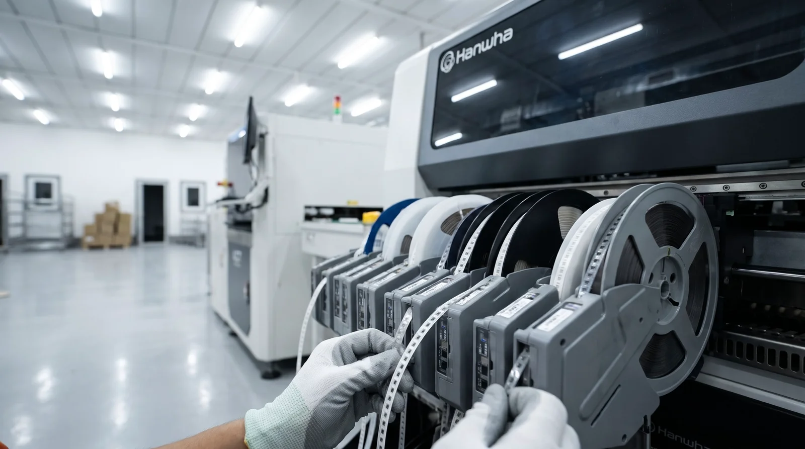
Packaging form is the first fork in feeder selection, and it is a fork because each form demands a physically different feeder. Tape and reel, tray, stick and bulk are not variations on a theme; they are four different presentation mechanisms, and a machine configured for one will not place a component supplied in another without the right feeder installed. This is why the packaging field on the BOM matters so much: it tells you, before you buy anything, which feeder classes the machine must support and how many of each the product list will consume.
This chapter works through the four packaging forms and the feeder types that present them, from the electric and pneumatic tape feeders that carry most chips and small ICs, through tray and matrix-tray feeders for BGAs and large parts, to the stick and bulk feeders that still serve odd-form components. It closes with a mapping table that turns the discussion into a lookup, so each component on the BOM can be matched to a feeder class with confidence. Getting this mapping right is the heart of Hanwha pick and place feeder and nozzle selection, because the feeder is only useful if it can present the exact packaging the supplier ships.
Tape-and-reel is the dominant packaging for surface-mount components, and the tape feeder is the workhorse of the feeder bank. The tape carries components in pockets at a fixed pitch, the feeder indexes it forward one pitch at a time, peels the cover tape, and presents each pocket at the pickup window. Tape feeders come in two broad drive types. Electric feeders use a motor to index the tape, which gives precise pitch control, programmable advance and reliable performance across tape widths and pitches; they are the modern default for high-mix and high-accuracy work. Pneumatic feeders use air to actuate the indexing mechanism, which is cheaper per feeder but less precise and more sensitive to air supply quality.
The choice between electric and pneumatic depends on the mix and the accuracy required. Electric feeders such as a Hanwha SMT electric tape feeder dominate where pitches are fine, where changeovers are frequent, and where the program needs to control advance precisely per component. Pneumatic feeders still make sense for coarse-pitch, high-volume, cost-sensitive work where the air supply is reliable. For most Hanwha lines building a mixed product list, the feeder bank is predominantly electric, with pneumatic feeders reserved for specific coarse parts or legacy positions, because the precision and programmability of electric drive is what keeps pickup reliability high across a wide component range.
Trays are the packaging of choice for components too large, too fragile or too valuable to tape — BGAs, large QFNs, some fine-pitch connectors and many odd-form parts. A tray holds components in a matrix of cells, and a tray feeder presents the matrix to the pickup head, either by moving the tray under a fixed pickup position or by moving the head across a static tray. Matrix-tray feeders, which hold several trays in a magazine and index them automatically, are the practical solution for production because they let the machine run through multiple trays without an operator reloading after each one.
The constraints that matter for tray selection are the matrix dimensions, the cell pitch, the tray material and the stacking arrangement. A tray feeder sized for one matrix will not hold a tray with a different cell pitch, and a magazine sized for one tray thickness will jam on a thicker one. The planner has to confirm, per tray component, the exact tray part number, matrix size and cell pitch, and then confirm that the feeder and magazine support them. Because trays are often used for the highest-value parts, a tray feeder that mispresents a BGA is an expensive failure, so tray selection is where precision in the BOM reading pays off most directly.
Stick feeders, also called tube feeders, present components that arrive in tubes — still common for some connectors, odd-form parts and legacy components. The feeder holds the tube at an angle so gravity feeds parts to the pickup end, and the head picks from the end of the tube. Stick feeders are simple and cheap, but they are also the least precise: part position at the pickup end varies with how full the tube is, parts can jam, and orientation depends on the tube geometry. For this reason stick feeders are used where nothing better exists, and their components usually need extra pickup tolerance or a dedicated nozzle.
Bulk feeders, which present loose components from a hopper or vibratory bowl, are the rarest form and are used mainly for mechanical parts, hardware and a few odd components that cannot be taped or trayed. They are inherently the least controllable, because loose parts have no fixed presentation and the feeder must singulate and orient them, which is why bulk feeding is usually a last resort and often handled outside the main placement flow. For a Hanwha line, the practical rule is to minimise stick and bulk feeding, convert to tape or tray where the supplier allows, and reserve the remaining stick and bulk positions for the few components that genuinely need them.
The mapping from packaging to feeder class is best kept as a simple lookup, because the same question comes up for every part on every new BOM. The table below pairs the common packaging forms with the feeder class that presents them and the main constraint to confirm. It is deliberately short, because the point is not to catalogue every feeder variant but to give the planner a fast way to classify each component before the detailed specification work begins.
Packaging form | Feeder class | Typical components | Main constraint to confirm |
|---|---|---|---|
Tape and reel (8–12 mm) | Electric / pneumatic tape feeder | 0402–1206 chips, SOT, small IC | Tape width, pitch, pocket depth |
Tape and reel (16–24 mm+) | Wide tape feeder | Large IC, connector, module | Pocket size, cover-tape type |
Tray / matrix tray | Tray or matrix-tray feeder | BGA, large QFN, odd-form | Matrix size, cell pitch, tray thickness |
Stick / tube | Stick (tube) feeder | Connector, odd-form, legacy part | Tube geometry, orientation, jamming risk |
Bulk / loose | Vibratory / bulk feeder | Hardware, mechanical part | Singulation, orientation, speed |
Used well, the table is a one-line check per component: read the packaging, read the feeder class, confirm the constraint. A part that classifies cleanly moves forward; a part that does not classify, or whose constraint cannot be confirmed, becomes a risk item to resolve before the feeder order. The discipline of classifying every BOM line this way is what turns a vague feeder package into a specific, verifiable feeder plan, and it is the step most often skipped when a line is bought on a standard configuration and later found to be short of the feeders the real product list needs.
If the feeder decides how a component arrives, the nozzle decides whether the machine can pick it up and put it down cleanly. Nozzle selection is a matching problem across three dimensions: the component's size and mass, its package geometry, and the accuracy and speed the placement demands. A nozzle that is right for a 0402 chip is wrong for a QFP, and a nozzle that is right for a QFP is wrong for a large connector. The machine head can carry a set of nozzles, and the program assigns one to each component, so the nozzle set and its assignment are as much a selection task as the feeder bank.
This chapter works through nozzle selection from the component outward. It explains how bore and tip size must track component size, how the major package families map to specific nozzle types, how fine-pitch and ultra-small chips demand their own nozzles, and how nozzle material and wear affect compatibility over time. It closes with a package-to-nozzle mapping table. Because nozzle and feeder decisions are made together, this chapter continues the same Hanwha pick and place feeder and nozzle selection discipline, now applied to the interface above the component rather than below it.
Nozzle size has two dimensions that both matter: the bore, which determines how much vacuum area is available to hold the part, and the tip, which determines how the nozzle seats against the component body without damaging it. For a small chip, a large bore picks up too much air around the part and may pick two components or none; for a large part, a small bore cannot hold the component against the acceleration of the head. The rule is that the bore should be sized to the component body so the vacuum grips the part securely without extending past its edges, and the tip should seat flat on the body without pressing on fragile features.
The tip geometry matters as much as the bore. A flat tip works for most rectangular chips and ICs; a tip with a conformal or rubber insert helps with uneven or delicate surfaces; a tip with a narrow extension reaches into recessed packages. Selecting the wrong tip profile produces placement errors that look like accuracy problems but are really seating problems — the part sits slightly off, rotates, or lifts on release. Matching bore and tip to the component's real body size and surface, rather than to a generic package name, is what keeps pickup and placement consistent across a mixed product list.
Most components fall into a small number of package families, and each family has a nozzle type that suits it. Standard chip packages — 0402, 0603, 0805, 1206 — use simple flat chip nozzles sized to the body. Small-outline transistors and small ICs use slightly larger chip or IC nozzles. QFPs and SOPs use rectangular nozzles that cover the body without touching the leads. BGAs use nozzles sized to the package body, often with a compliant tip to seat on the ball array. LEDs use nozzles that avoid the lens, and connectors and odd-form parts use custom or extended nozzles. A machine that builds a mixed board needs the full set, and the program must assign each component to the correct nozzle.
The practical consequence is that nozzle selection is a set problem, not a single choice: you are specifying the nozzle kit the machine carries, and the kit has to cover every package family on the product list. A machine such as the Samsung SM482 Plus high-speed mounter is often specified with a nozzle kit matched to the mix it will run, precisely because a generic kit leaves gaps that show up as pickup failures on the parts outside it. Specifying the kit against the real package list, family by family, is what prevents those gaps.
The smallest components demand the most precise nozzles, and they are where nozzle selection stops being routine. A 0201 or 01005 chip is small enough that a standard chip nozzle will not seat reliably, and the pickup must be centred to within a fraction of the part's own size. Fine-pitch nozzles for these parts have a small bore, a precisely machined flat tip and often a compliant element to absorb the tiny misalignments between feeder presentation and head descent. Using a larger nozzle on these parts produces mispicks, double picks and tombstoning that no amount of program tuning will fully fix.
Fine-pitch ICs pose a different challenge: the nozzle must grip the body without touching the leads, and the placement must be accurate enough for the lead pitch. This is where nozzle condition matters most, because a worn or contaminated fine-pitch nozzle loses its seal and drops parts intermittently, and the defect rate creeps up without an obvious cause. Selecting fine-pitch nozzles is therefore only half the job; the other half is managing their wear and cleanliness, which is why nozzle selection and nozzle maintenance are treated together in any serious feeder and nozzle plan.
Nozzle material affects life, pickup reliability and component safety. Ceramic nozzles resist wear and hold their tip geometry well, which suits high-cycle fine-pitch work. Tungsten-carbide and hardened-steel nozzles are durable for general use. Rubber or compliant tips protect delicate or uneven components but wear faster and need replacement. Anti-static and conductive materials matter for ESD-sensitive parts, because a nozzle that accumulates charge can damage or displace small components. The material choice is a trade between wear life, pickup quality and component protection, and it should follow the component mix rather than a default.
Wear is the hidden variable in nozzle selection. A nozzle that was correct at installation gradually loses its tip flatness, its bore edge and its seal, and the first symptom is a rising mispick rate on the parts it handles. Nozzle compatibility is therefore not a one-time match but an ongoing condition: the nozzle set must be inspected, cleaned and replaced on a schedule tied to cycle count and component type. The table below summarises the package-to-nozzle mapping that anchors the selection, and the platforms it runs on are part of the wider Samsung pick and place machine range that shares feeder and nozzle families across models.
Package family | Nozzle type | Bore / tip note | Watch-out |
|---|---|---|---|
0402–1206 chip | Standard chip nozzle | Bore matched to body width | Oversize bore double-picks |
0201 / 01005 | Ultra-small fine nozzle | Small bore, flat precise tip | Centring, tombstoning |
QFP / SOP | Rectangular IC nozzle | Body-covering, lead-safe | Lead contact, skew |
BGA / CSP | BGA nozzle, compliant tip | Body-sized, flat seat | Ball damage, seating |
LED | Lens-safe nozzle | Avoids optical surface | Lens damage, tilt |
Connector / odd-form | Custom / extended nozzle | Reaches recessed body | Grip area, mass |
Treated as a lookup, the table lets the planner assign a nozzle family to every BOM line before the machine is configured, and it exposes the parts that need a custom nozzle early enough to order one. The nozzle kit is then the union of these families plus spares for the highest-wear types. That union, checked against the machine's nozzle capacity and the program's assignment rules, is the nozzle half of the feeder and nozzle plan.

Between the packaging form and the finished feeder plan sits a layer of logistics that buyers routinely underestimate: tape width and pitch, reel diameter, tray matrix, splicing, moisture and ESD handling, and the storage and kitting that keep the feeder bank fed. These details do not change the feeder class, but they decide whether the chosen feeder can actually hold and advance the tape, how often the line stops to change reels, and whether a moisture-sensitive part is still good when it reaches the nozzle. They are the difference between a feeder plan that works on paper and one that works on the floor.
This chapter covers those logistics in the order they affect the line: tape geometry and what it constrains, reel diameter and splicing for run length, tray matrix and the handling that protects sensitive parts, and the storage and kitting that keep changeovers fast. It is the practical complement to the feeder-class mapping of the previous chapters, and it completes the feeder side of Hanwha pick and place feeder and nozzle selection before the guide turns to component risk.
Tape is specified by width, pitch and pocket geometry, and each constrains the feeder that can handle it. Width (commonly 8, 12, 16, 24 and 32 mm) determines which feeder slot and which feeder body will accept the tape; a feeder built for 8 mm tape will not take a 16 mm tape without a different feeder or a conversion. Pitch — the distance between pockets — determines the index step the feeder must advance, and a feeder programmed for the wrong pitch will present components off-centre. Pocket geometry determines whether the component sits at the right depth for the nozzle to reach it without crushing it.
These constraints are why the planner confirms tape width and pitch per part rather than assuming a standard. A reel that looks standard may be a non-standard width, and a tape that looks like 8 mm may have a pitch the feeder does not support. Confirming width, pitch and pocket depth against the supplier's tape drawing, and matching them to the feeder's supported range, prevents the discovery at the machine that a feeder cannot advance a particular tape. It is a small check per part that saves a large disruption when the line is supposed to be running.
Reel diameter looks like a minor detail until the line stops every twenty minutes to change a small reel. Reels come in standard diameters (commonly 7, 13 and 15 inches), and the diameter sets how many components a reel carries, which sets how long the line can run before a reload. For high-volume parts, a larger reel reduces reload frequency; for low-volume parts, a smaller reel avoids carrying excess inventory that may go out of date. Matching reel diameter to the part's consumption rate is part of sizing the feeder plan for uptime rather than just for placement.
Splicing and packaging standards complete the logistics. Splicing lets a new reel be joined to a running tape so the line does not stop, but it requires matching tape and pocket geometry and a splice that the feeder can pass without jamming. Packaging standards — tape-and-reel conventions, reel labelling, and the EIA-481 style conventions many suppliers follow — determine whether the reel will interface cleanly with the feeder and whether the label carries the data the line needs. Confirming these standards per supplier, especially for new parts, keeps the feeder bank running without splice jams and reload stops.
Trays add their own logistics. The matrix size and cell pitch determine which tray feeder and magazine will hold the tray, and the tray material and thickness determine how it stacks and indexes. Because trays often carry the most expensive and most moisture-sensitive parts — BGAs in particular — the handling around them matters as much as the feeder. A tray that is opened and left out absorbs moisture, and a moisture-sensitive BGA that is reflowed wet can crack or delaminate, so tray logistics has to include moisture control, not just presentation.
ESD handling is the other half. Trays and the components in them are ESD-sensitive, and the feeder, the nozzle and the operator all have to be part of a controlled ESD path. Trays should be stored and handled in ESD-safe conditions, and the feeder and nozzle materials should be chosen with ESD in mind where the parts demand it. Moisture sensitivity level, bake schedules and floor-life limits belong on the tray component's handling record, and the feeder plan should reflect them. A tray feeder that presents a part perfectly but lets it absorb moisture has solved the wrong problem.
The feeder bank is only as good as the storage and kitting behind it. Components have to be stored so that a reel or tray can be retrieved, verified and loaded quickly, and the kitting process has to assemble the next order's feeders off-line so the line does not stop while a set is built. A practical feeder and nozzle plan includes the storage layout — reels by part number, trays by moisture class, nozzles by type — and the kitting workflow that pre-loads the next order's feeders on a cart while the current order runs.
Changeover logistics ties the whole feeder plan together. Where feeders are standardised so the same component always sits in the same slot, and where the next order is kitted in advance, changeover becomes a swap rather than a rebuild. Where they are not, every changeover is a fresh setup and the feeder plan's benefit is lost. The SMT tape feeder lineup for Hanwha and Samsung matters here because a consistent feeder family across the bank is what makes slot standardisation and pre-kitting practical, and that consistency is the logistics payoff of getting feeder selection right.
A feeder and nozzle plan that looks complete on paper still has to survive the floor, where the risks are not the tidy categories of the selection process but the messy realities of a wrong reel loaded into a feeder, a feeder that has drifted out of calibration, a nozzle that has quietly worn, and a moisture-sensitive part that sat out too long. These risks do not appear in the BOM or the feeder list, but they are what actually cause the mispicks, wrong-part placements and intermittent defects that erode yield on a running line. Error-proofing is the discipline of catching them before they reach the board.
This chapter maps the main component risks to the controls that catch them. It covers wrong-reel and wrong-feeder risk, feeder calibration and pickup reliability, nozzle wear and clogging, and the vision, moisture and ESD gates that close the remaining gaps. It closes with a risk-to-control table that turns the discussion into a checklist. This is the quality-control layer of Hanwha pick and place feeder and nozzle selection, the part that keeps a correct selection correct in daily production rather than only at installation.
The most expensive feeder error is also the simplest: the wrong reel loaded into the right feeder, or the right reel loaded into the wrong slot. Either produces a board full of the wrong component, and because the placement looks mechanically perfect, the defect is only caught at inspection or test, by which time the boards may be built and the parts consumed. Wrong-reel risk rises with the number of part numbers and the frequency of changeover, because every swap is an opportunity to load a reel that looks similar to the one intended — same package, same colour, different value.
The controls are routine but must be enforced. Barcode scanning of the reel against the feeder slot and the program is the strongest control, because it removes the manual match that fails under time pressure. Where scanning is not available, a two-person verification of reel against slot map, and a first-article check after every changeover, catch most errors. Standardising feeder slots so a part always sits in the same position reduces the decision space and therefore the error rate. The point is not to trust the operator to be careful but to design the process so a wrong reel is hard to load and easy to catch.
Feeders drift. A tape feeder that was calibrated at installation gradually loses its index accuracy as the mechanism wears, the tape path collects debris and the pickup height shifts. The result is a slow decline in pickup reliability that shows up as a rising mispick count rather than a single failure, and because it is gradual it is easy to normalise. Feeder calibration — checking index position, pickup height and cover-tape peel against a reference — is what catches the drift before it becomes a defect source.
Calibration should be scheduled by cycle count and by component type, with tighter intervals for fine-pitch and small-chip feeders where a small drift matters most. The calibration itself is quick on modern electric feeders, which can be checked and adjusted without removing them from the bank, but the discipline of doing it on schedule is what matters. A feeder bank that is calibrated on a schedule runs at a stable pickup rate; one that is calibrated only when problems appear runs at a rate that quietly declines. Treating calibration as routine maintenance rather than emergency repair is the difference between the two. On a pre-owned machine, feeder and nozzle condition is part of what the verifying a pre-owned Hanwha mounter inspection establishes before the machine is trusted with production, so calibration and condition are checked together.
Nozzles fail in ways that are easy to miss. The tip wears and loses its flat seal, so the vacuum leaks and the part drops or sits off-centre. The bore clogs with flux residue, dust or component debris, so the vacuum drops and the pickup becomes intermittent. The spring or compliant element loses its travel, so the nozzle no longer seats properly on uneven parts. None of these produces an obvious alarm; all of them produce a rising defect rate on the parts the affected nozzle handles, which is why nozzle condition has to be inspected rather than assumed.
The controls are inspection, cleaning and replacement on a schedule tied to cycle count and component type. Fine-pitch and small-chip nozzles need the most frequent inspection because their margins are smallest. Cleaning removes flux and debris before it hardens; inspection catches wear before it becomes a seal failure; replacement retires a nozzle before it starts dropping parts. A nozzle that is past its wear limit is not a nozzle that is slightly worse — it is a nozzle that will fail intermittently, and intermittent failures are the most expensive kind because they pass first-article checks and fail in volume. Managing nozzle condition is therefore a direct lever on yield, not housekeeping.
The remaining risks are caught by gates rather than by the feeder or nozzle directly. Vision systems verify component presence, orientation and, on some machines, polarity, catching the wrong-part and wrong-orientation errors that feeder controls might miss, and the final solder acceptability of those placements is judged against IPC-A-610 at inspection. Moisture-sensitive devices need a bake and floor-life gate, because a part that has absorbed moisture can fail at reflow even though it was placed correctly. ESD controls protect the part from charge damage during handling, feeding and placement, and an ESD-safe feeder and nozzle path is part of that control. Each gate catches a class of risk the mechanical controls cannot.
These gates belong in the feeder and nozzle plan because they are part of the same interface chain. A program that verifies component presence but not polarity leaves a gap; a feeder plan that ignores moisture sensitivity leaves a gap; a nozzle set that is not ESD-rated where the parts demand it leaves a gap. The table below pairs the main risks with their controls, so each can be checked as part of the selection rather than discovered in production. Closing these gates is what turns a mechanically correct feeder and nozzle set into a process that reliably builds good boards.
Risk | Typical symptom | Primary control |
|---|---|---|
Wrong reel / wrong slot | Wrong component, correct placement | Barcode verify, slot standardisation, first article |
Feeder drift | Rising mispick on one lane | Scheduled calibration by cycle count |
Nozzle wear / clog | Intermittent drop, offset, tombstone | Inspect, clean, replace on schedule |
Wrong orientation | Rotated or reversed part | Vision presence and polarity check |
Moisture (MSD) | Reflow cracks, delamination | Bake and floor-life gate (J-STD-033) |
ESD damage | Latent or immediate part failure | ESD-safe feeder, nozzle, handling |
By this point the selection has produced a feeder class for every packaging form, a nozzle family for every package, a logistics plan for tape, reel and tray, and a set of risk controls. The last step is to verify that all of it holds together as one plan before the line is committed, because each decision was made in isolation and the failures that matter are the ones at the seams — a part whose feeder exists but whose nozzle does not, a tray component with no moisture gate, a feeder plan that exceeds the machine's slot count. Verification is where the pieces are checked against each other rather than against their own chapter.
This chapter walks through the verification in three passes: building a cross-reference matrix that ties every component to its feeder, nozzle and control; running a trial that proves pickup and placement on the real board; and signing off with the documentation that lets the plan be maintained. It ends with a short section on keeping the selection valid as the product list changes. This is the closing discipline of Hanwha pick and place feeder and nozzle selection, and it is what converts a set of good decisions into a line that builds good boards from the first shift.
The cross-reference matrix is a single table, one row per component, that lists the feeder class, the nozzle family, the packaging constraint and the risk control for that component. Its value is that it forces every interface to be filled in for every part, so a gap cannot hide between chapters. A row with a feeder but no nozzle is a part the machine cannot place; a row with a nozzle but no moisture gate is a part that can fail at reflow; a row whose feeder class exceeds the machine's supported types is a part the line cannot feed. Building the matrix is the act of checking the plan against itself.
The matrix also sizes the plan. Counting rows by feeder class gives the feeder budget; counting by nozzle family gives the nozzle kit; counting parts that need special handling gives the risk-control workload. Because it is one table, it can be reviewed with purchasing, process and the machine supplier together, and disagreements surface as rows rather than as arguments. A plan that can be expressed as a complete matrix is a plan that can be quoted, ordered and verified; a plan that cannot be reduced to one is still a collection of assumptions.
A matrix proves the plan is complete; a trial proves it works. The trial loads the actual feeders and nozzles and runs the actual board, then measures pickup rate, placement accuracy and defect rate against the plan's targets, with placement performance referenced to IPC-9850 where the machine's acceptance uses that equipment standard. Pickup rate exposes feeder presentation and nozzle seating problems; placement accuracy exposes nozzle and vision problems; defect rate exposes the seam between them. The trial should use the real components, because substitute parts with different packaging or body size will not exercise the interfaces the plan was built around.
The trial run is also where the risk controls get exercised. Wrong-reel controls are tested by loading a deliberately mismatched reel and confirming the scan catches it; nozzle condition is checked by inspecting the nozzles after the run; moisture and ESD gates are confirmed against the components that need them. A trial that only measures throughput misses the point of verification, which is to prove the plan holds under the conditions that will actually produce defects. Running the trial to the point where the interfaces are stressed, not just to the point where boards come out, is what makes it a verification rather than a demonstration.
Sign-off converts the verified plan into a controlled asset. It records the feeder classes, nozzle families, packaging constraints and risk controls as the approved configuration, together with the calibration and inspection schedules that keep them valid. The record should be specific enough that a new engineer can reconstruct the plan, and it should be tied to the machine acceptance so that the feeder and nozzle configuration is part of what was accepted, not a separate note. The Hanwha mounter FAT and SAT acceptance process is the natural home for this, because feeder and nozzle verification is part of proving the machine meets its specification on the real product.
Documentation is what prevents the plan from eroding. Without a record, feeder slots get reassigned, nozzles get swapped without notes, and calibration intervals get forgotten, and within a few months the verified plan has drifted back into an ad-hoc arrangement. The signed record, kept with the machine and updated when the product list changes, is the reference that keeps the selection honest. It is unglamorous, but it is the difference between a plan that was correct once and a process that stays correct, which is the whole point of doing the selection properly in the first place.
Feeder and nozzle selection is not a one-time event, because the product list changes. New part numbers arrive, old ones retire, packaging changes when a supplier switches tape or tray format, and the feeder and nozzle plan has to follow. A plan that is not revisited becomes stale, and a stale plan is worse than no plan because it gives false confidence — the line believes it is configured for the product when it is configured for last year's product. Keeping the selection valid means treating the cross-reference matrix as a living document and updating it whenever the BOM changes.
The practical routine is to re-run the matrix and the trial for any new component family, and to check the packaging and handling for any changed part number. A new BGA with a different tray matrix, a part that has moved from tray to tape, a component that now needs a finer nozzle — each is a change the plan must absorb. Building this review into the new-product introduction process, so that the feeder and nozzle plan is updated before the part reaches the line, is what keeps the selection permanently valid. Done this way, the plan does not decay between audits; it evolves with the product, and the line stays configured for what it actually builds.
Get the feeder and nozzle set right before the first board
Feeder and nozzle selection is where a Hanwha line either runs at its quoted speed or quietly loses a shift to a hundred small pickup errors, and the work that prevents that loss is done before the machine is ordered, not after the first defect report. The method in this guide is deliberately unglamorous: read the BOM properly, classify every component by packaging form, match component size and package family to the right nozzle, confirm the tape, reel and tray logistics, close the wrong-reel, wear, moisture and ESD gates, and verify the whole plan against the real board before sign-off. A team that does these steps ends up with a feeder and nozzle set that is complete for its product list, repeatable across changeovers and cheap to maintain, which is a far better outcome than a standard feeder package that looked competitive on the quotation and turned out to be short of the parts the line actually runs. If you are specifying a new Hanwha machine or reconfiguring an existing one, the practical next step is to build the cross-reference matrix for your current BOM and see where the gaps are — the parts with no feeder, the packages with no nozzle, the trays with no moisture gate — because those gaps are exactly what the selection is meant to close, and the boards you really build are the right place to start.
Start from the packaging form, not the part number. Tape and reel needs a tape feeder matched to the tape width and pitch; trays need a tray or matrix-tray feeder matched to the matrix size and cell pitch; tubes need a stick feeder; loose parts need a bulk feeder. Then confirm the constraint for that class — tape width, pocket depth, tray thickness, tube geometry — against the supplier's packaging drawing. A component whose packaging does not map cleanly to a supported feeder class is a component the machine cannot feed, so resolve it before the feeder order rather than after.
Ultra-small chips need a dedicated fine nozzle with a small bore and a precisely machined flat tip, not a standard chip nozzle scaled down. The bore must be sized to the tiny body so the vacuum grips the part without extending past its edges, and the tip must seat flat to keep the part centred during pickup and travel. Because the margins are so small, these nozzles also need frequent inspection and cleaning, and their wear has to be managed on a tighter schedule than general nozzles. Using a general chip nozzle on 0201 or 01005 parts produces mispicks and tombstoning that program tuning cannot fully fix.
Electric feeders are the modern default for most mixed and fine-pitch work because they give precise, programmable pitch control and reliable performance across tape widths and pitches. Pneumatic feeders are cheaper per unit and still make sense for coarse-pitch, high-volume, cost-sensitive parts where the air supply is reliable. For a Hanwha line building a mixed product list, the feeder bank is usually predominantly electric, with pneumatic feeders reserved for specific coarse or legacy positions. The deciding factors are pitch precision, changeover frequency and how much the program needs to control feeder advance per component.
Plan for more than the minimum, because a healthy line keeps spares moving through calibration and repair. A practical rule is enough feeders to cover the largest single order's distinct components, plus a second kitted set for staging, plus a buffer for feeders out for calibration or wear. For nozzles, keep spares of the highest-wear types — fine-pitch and small-chip nozzles — so a worn nozzle can be swapped immediately rather than waiting for a replacement. The spare pool should follow the component mix, not a generic percentage, because a line dominated by fine-pitch parts consumes fine nozzles far faster than a line of coarse chips.
Base the interval on cycle count and component type rather than calendar time alone. Feeders should be calibrated on a schedule tied to how many cycles they run, with tighter intervals for fine-pitch and small-chip feeders where drift matters most. Nozzles should be inspected and cleaned on a similar cycle-count basis, and replaced when the tip flatness, bore edge or seal is worn past its limit. Fine-pitch and small-chip nozzles need the most frequent attention. Using calendar time alone lets heavily used feeders drift between checks and lightly used ones be serviced needlessly, so cycle count is the better driver.
Use barcode scanning of the reel against the feeder slot and the program as the primary control, because it removes the manual match that fails under time pressure. Where scanning is not available, require a two-person verification of reel against slot map and a first-article check after every changeover. Standardising feeder slots so a part always sits in the same position also reduces the decision space and the error rate. The goal is to design the process so a wrong reel is hard to load and easy to catch, rather than relying on the operator to be careful on every swap.
Feeder selection is about how the component arrives at the pickup point — it matches the packaging form (tape, tray, tube, bulk) and its constraints to a feeder class. Nozzle selection is about how the component is picked and placed — it matches the component's size, package family and surface to a nozzle bore and tip. The two are decided together because they are the two interfaces that touch the component, but they answer different questions: the feeder decides whether the part can be presented, the nozzle decides whether it can be picked and placed cleanly. A complete Hanwha pick and place feeder and nozzle selection covers both, part by part.
Yes, if the set covers the union of the component families across those boards and the machine has enough feeder positions for the largest board's distinct part numbers. The practical approach is to standardise feeder slots so the same component always sits in the same position, keep a nozzle kit that covers every package family in the union, and pre-kit the next order's feeders off-line so changeover is a swap rather than a rebuild. The set then serves several boards without a full reconfiguration, which is exactly why feeder and nozzle selection is done against the whole product list rather than one board at a time.