English
Views: 0 Author: Elsa Long Publish Time: 2026-10-29 Origin: Site


LED PCB assembly is often treated as an easy product, because an LED lighting board carries relatively few part numbers and a large fraction of its placements are the same chip or lens. That reputation is misleading. The boards are long, often thin, sometimes heavily panelised, and they carry components with optical geometry and significant height, so the machine that places them well is not the fastest general-purpose mounter but one whose envelope, support, nozzle set and line integration actually fit the LED product. Choosing the right Hanwha pick and place machine for LED PCB assembly means evaluating the equipment against six LED-specific axes — long-board handling, lens geometry, component height, board support, cycle time and full-line support — rather than against a headline CPH number. The hardware context is the Hanwha pick and place equipment lineup, and this guide turns those six axes into concrete evaluation criteria.
The guide is organised the way a real LED project is evaluated. It starts with why LED boards are a different selection problem, then reads the LED product itself — board length, panel design, materials and placement counts — before working, chapter by chapter, through each evaluation axis: long-board envelope and handling, LED lens and component-height placement, board support and warpage control, cycle time and throughput, and full-line support from reflow to inspection. It finishes with a machine evaluation and acceptance checklist that ties the axes together and a set of frequently asked questions. Throughout, the aim is a selection method that survives contact with the real product, so the machine you choose places LED boards at the yield and rate the project actually needs, rather than at the rate a datasheet promised for a different board.
Table of Contents
A general SMT mounter is chosen for its speed, its accuracy and its component range, and those numbers are quoted for a typical board — moderate size, thin components, a mix of chips and small ICs. LED lighting boards break that assumption in several directions at once. They are long, often very long, because a lighting fixture wants a long strip of LEDs on one board. They carry components with optical geometry — lenses and domes — that must be placed without damage and with alignment that matters to the final light output. They often sit on thin, wide panels that warp, and they are frequently built in high volume, so cycle time matters. A mounter that is excellent on a standard control board can be merely adequate, or actively wrong, on an LED board.
This chapter explains why LED assembly deserves its own selection criteria and sets out the six axes the rest of the guide will examine. It looks at how LED boards differ from standard SMT boards, why a general-purpose mounter can miss the mark on them, and how to read the following chapters against your own product rather than against a generic example. The point is not that LED boards are uniquely difficult but that their difficulty is concentrated in specific dimensions — length, height, optics, support and line integration — and Hanwha pick and place machine for LED PCB assembly selection is the discipline of checking those dimensions explicitly rather than trusting a general specification.
LED equipment selection can be reduced to six axes, and every one of them has a concrete evaluation item behind it. Long-board handling asks whether the machine's board envelope and conveyor can carry the panel without sag or misalignment. LED lens geometry asks whether the nozzle and placement accuracy can seat an optical component without damaging it or skewing its light axis. Component height asks whether the machine's nozzle clearance and head travel can place tall parts alongside flat ones. Board support asks whether the panel can be held flat enough for accurate placement across its length. Cycle time asks whether the real placed-component rate meets the volume, not the datasheet rate. Full-line support asks whether reflow, conveyor and inspection are matched to the LED process rather than bolted on.
Treating the six as a checklist is what separates a considered selection from a hopeful one. Each axis has a measurable evaluation item — envelope in millimetres, lens height in millimetres, panel warpage in millimetres, placed-component rate at the real mix, line interface standard — so the selection can be argued with data rather than impressions. A machine that passes all six on your actual LED panel is a machine that will build the product; a machine that passes five and is marginal on the sixth is a machine that will build it with a problem you already know about. Naming the axes up front makes that trade-off explicit instead of discovering it after installation.
The differences are physical and they compound. Length is the most obvious: an LED strip board may run from a few hundred millimetres to well over a metre, and the machine envelope and conveyor have to accommodate that length without the panel flexing under the placement head. Thickness is the second: LED boards are often thin to save material and cost, which makes them prone to warpage and means the support system has to work harder. Component height is the third: lenses and domes stand several millimetres above the board, so the nozzle approach and the head travel have to clear neighbouring tall parts while still placing accurately.
Optical alignment is the fourth difference, and the one that catches general-purpose selections. An LED lens is not just a component; its placement affects where the light goes, so a small rotational or positional error that would be acceptable on a decoupling capacitor is a visible defect on a lens. Combine that with high placement counts and a long panel and the result is a board where both accuracy and speed matter, and where the tolerance for a marginal nozzle or a sagging panel is much tighter than on a standard product. These differences are why LED assembly rewards a machine evaluated on its own terms.
A general-purpose mounter is optimised for a broad component mix on moderate boards, and that optimisation can work against an LED product. Its board envelope may be generous enough for a standard panel but marginal for a metre-long LED strip. Its support system may be designed for a rigid board and struggle with a thin, warped panel. Its nozzle set may cover chips and ICs but handle a tall, domed lens badly. None of these is a defect in the machine; they are simply mismatches between a general design and a specific product, and they only surface when the machine meets the real LED panel.
The practical consequence is that a buyer who selects on CPH and component count alone can end up with a machine that is fast on paper and constrained in practice — limited by envelope, by support, by nozzle clearance or by lens handling. That is why the evaluation has to go beyond the headline specification and into the specific items that LED boards stress. A machine chosen this way may not be the fastest in the catalogue, but it will be the one that places the LED panel at the rate and yield the project needs, which is the only measure that matters once production starts.
No guide can select a machine for you, because the right answer depends on your panel, your volume and your line. What a guide can do is give you the evaluation items and the questions to ask, so that your own data drives the decision. As you read the following chapters, keep your actual LED board in view: its length and thickness, its lens and component heights, its panel design and placement count, its target volume and its downstream equipment. Each chapter's criteria should be applied to that board, not to a generic example, and where a criterion cannot be met, that is a finding worth acting on before the machine is ordered.
This is the same evidence-based discipline that governs Hanwha mounter selection guide for any product, applied to the LED case. The difference is the weight given to length, optics, height and support, which on a standard board are secondary and on an LED board are decisive. Read the chapters as a structured interrogation of your product and your candidate machines, and the selection that comes out of it will be defensible to your process team, your finance team and the customer who will inspect the light output.
Board length is the first axis because it is the hardest to work around. A machine's board envelope — the maximum length and width it can carry — is a hard physical limit, and an LED strip that exceeds it simply cannot be placed on that machine, no matter how good the rest of its specification. But envelope is only the entry condition; even within the envelope, a long thin panel has to be carried without sag, held flat for placement, and moved through the conveyor without misalignment. Long-board handling is therefore both a dimension check and a mechanical one.
This chapter examines the envelope and handling requirements for LED boards. It covers board length and the machine envelope, panel design and conveyor support for long boards, the trade-offs of multi-up panels, and how to verify the envelope against the real panel rather than a nominal figure. The aim is to turn "can this machine handle my board?" from an assumption into a checked answer, which is the first concrete step in selecting Hanwha pick and place machine for LED PCB assembly equipment that fits the product.
The machine envelope is specified as a maximum board length and width, and for LED work the length figure is the one that decides. An LED strip board can run from a few hundred millimetres to well over a metre, and a machine rated for a shorter board cannot place it without a different configuration or a panel redesign. The envelope check is therefore the first filter: list your longest board, add any panel margin, and confirm the candidate machine's maximum length exceeds it with headroom for the conveyor and clamping.
The check has to use the real board, not an average. LED product lines often include several lengths, and the machine must handle the longest, because a machine that fits most of the range but not the flagship strip is a machine that forces a panel split or a second machine. The same logic applies to width, especially on multi-up panels, where the panel width may exceed a single board's. Confirming envelope against the longest and widest panel in the product family, rather than against a typical board, is what prevents the discovery that the machine cannot carry the product that matters most.
Within the envelope, the panel has to be carried and supported along its length. A long board is a lever, and if the conveyor or support holds it only at the ends, the middle sags under its own weight and under the placement force, which throws off placement height and accuracy. The conveyor therefore has to support the panel along its span, and the machine's support system has to be able to reach the middle of a long board, not just its edges. This is a mechanical requirement that a short-board machine may not have been designed for.
Panel design interacts with this. Breakaway tabs, V-scores and panel rails affect how the panel sits on the conveyor and how much support is available at the placement area. A panel designed without regard to long-board support can leave the crucial middle area unsupported, and no amount of machine adjustment fully compensates. Reviewing the panel design alongside the machine's conveyor and support capabilities — ideally before the panel is finalised — is what keeps the board flat where the LEDs are placed. Treating panel design and machine selection as one decision, rather than two separate ones, is part of getting long-board handling right.
Many LED products are built on multi-up panels to raise throughput, and that choice changes the handling requirements. A multi-up panel is wider and heavier than a single board, so the envelope and conveyor have to carry the larger panel, and the support has to cover the whole panel rather than one strip. The benefit is more boards per placement cycle; the cost is a larger, flatter panel that is harder to support and more sensitive to warpage. The trade-off has to be evaluated against the machine's real capabilities, not assumed to be free.
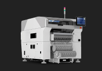
The decision also affects cycle time and yield. A multi-up panel that the machine can place accurately raises throughput, but a multi-up panel that sags or misaligns lowers yield and may cost more than the throughput gains. For a machine such as the DECAN S2 flagship SMT mounter, with a wide envelope and a robust support system, a multi-up LED panel is a realistic option; on a machine with a narrower envelope or lighter support, it may not be. Matching the panel strategy to the machine's handling capability is part of the long-board evaluation, not a separate downstream decision.
The final step in long-board evaluation is to verify the envelope against the actual panel, ideally with a physical check rather than a datasheet comparison. A drawing or a sample panel placed on the machine's conveyor tells you more than a specification table, because it exposes the interaction between panel length, conveyor support and clamping that a nominal envelope figure hides. Where a physical check is not possible before purchase, a trial at the supplier's facility with a representative panel is the next best thing.
The verification should record the longest and widest panel, the support coverage at the placement area, and any panel features that affect handling. If the machine passes, the long-board axis is closed with evidence; if it is marginal, the finding is a design input — a panel split, a different panel design or a different machine — rather than a surprise at installation. Verifying the envelope against the real panel is a small step that prevents a large problem, and it sets the pattern for the remaining axes: check against your product, with evidence, before you commit.

LED boards are defined by their optical components, and optical components are where a general-purpose placement assumption breaks down. A lens or a dome is taller than a chip, often fragile, and its placement is judged not only by whether it sits on its pads but by whether the light it emits points where it should. That makes LED lens placement a combined accuracy, height and handling problem, and it is the second axis of machine evaluation after long-board handling. A machine that places chips and ICs well may still mishandle a lens.
This chapter examines the lens and component-height axis in detail. It covers the geometry of LED lenses and the constraints they impose, the effect of component height on nozzle clearance and head travel, the placement accuracy required for LED pitch and alignment, and the nozzle and feeder implications that follow. It closes with a reference table of LED component types and their handling considerations. Together these turn "can this machine place LED optics?" into a set of specific checks, which is the core of Hanwha pick and place machine for LED PCB assembly evaluation for the optical side of the product.
An LED lens or dome is a three-dimensional optical element, and its geometry drives the placement constraint. The lens sits on the LED package and shapes the emitted light, so its rotational alignment and its seating height both affect the optical result. A lens placed slightly rotated sends light off-axis; a lens not fully seated changes the light distribution; a lens pressed too hard can crack or deform. These are not cosmetic issues on a lighting product, because the customer judges the board by its light output, not by its solder joints alone.
The practical constraint is that the nozzle must grip the lens by its body without touching or stressing the optical surface, and must place it with rotational accuracy tight enough for the optics. That rules out a generic chip nozzle and calls for a lens-specific nozzle and a placement strategy that respects the lens height. The lens geometry also affects feeder selection, because lenses are often supplied in trays or specialised tape that must present them without damage. Reading the lens datasheet for its height, seating face and optical axis, and matching the nozzle and feeder to those, is the concrete first step of the lens axis.
Component height is the axis that most often surprises a general-purpose selection. LED lenses and domes stand several millimetres above the board, and on a densely populated LED panel the nozzle must descend between tall neighbours to place the next part. If the machine's nozzle clearance and head travel cannot accommodate that, the nozzle collides with an already-placed lens or approaches at an angle that misplaces the part. The height check is therefore about the machine's Z-axis capability and the nozzle's physical envelope, not just the component's nominal height.
The check has to consider the tallest component and its neighbours, not the tallest component in isolation. A lens that is 5 mm tall is a problem if the nozzle body is wider than the gap between lenses, or if the head cannot retract high enough to clear a placed lens before moving to the next. The evaluation item is to map the tallest and densest region of the LED panel and confirm the machine's head and nozzle can operate there without collision. Where they cannot, the options are a different nozzle, a different placement order, a different panel layout or a different machine, and all of those are better decided before the order than after.
LED placement accuracy has two components: positional accuracy, so the lens sits on its pads, and rotational accuracy, so the optical axis points correctly. Both are tighter than a standard chip placement might suggest, because the LED pitch on a lighting board can be fine and the optical consequence of a small error is visible. A machine rated for fine-pitch IC placement usually has the positional accuracy for LED work, but the rotational accuracy and the repeatability across a long panel are what the evaluation should confirm.
The accuracy has to hold across the whole panel, not just at the centre. On a long board, any flex or misalignment grows from one end to the other, so an accuracy figure measured at the middle of a short test board may not represent the far end of a metre-long LED strip. The evaluation should check placement accuracy at multiple points along the real panel, including the extremes, and confirm it meets the LED pitch and alignment requirement there. Accuracy that holds across the full length is what the optical product needs, and it is a more demanding check than a single-point datasheet figure.
The lens and height constraints translate directly into nozzle and feeder requirements. The nozzle must match the lens body — gripping it without touching the optical surface, and sized so the vacuum holds it securely during travel. The feeder must present the lens without damage, which often means a tray feeder for domed lenses or a specialised tape feeder for flat ones, and the presentation must keep the lens upright and undamaged until pickup. These are the same feeder and nozzle disciplines described in the SMT feeder and nozzle selection guide, applied to optical components where the tolerances are tighter.
The implication for machine selection is that the candidate machine must support the nozzle and feeder types the LED components need. A machine with a limited nozzle range or a feeder platform that does not accept the lens packaging is not suitable, regardless of its speed. Confirming the nozzle and feeder compatibility for every LED component — the lens, the LED package, any driver ICs and passives — is part of the lens axis, and it is where the optical, mechanical and material considerations come together. The table below summarises the main LED component types and their handling considerations as a starting reference.
LED component | Typical packaging | Key handling consideration |
|---|---|---|
LED chip / package | Tape and reel | Polarity, pitch accuracy, nozzle size |
Lens / dome | Tray or specialised tape | Optical surface, seating height, rotation |
Driver IC | Tape and reel | Fine pitch, lead-safe nozzle |
Connector / terminal | Tape, tray or tube | Height, grip area, insertion force |
Passives (R/C) | Tape and reel | Standard chip nozzle, high count |
Used as a checklist, the table forces a handling consideration for every LED component before the machine is configured, and it exposes the parts that need a special nozzle or feeder early. It also shows where the evaluation is likely to bite: the lens row is the one that most often needs a non-standard nozzle and a tray feeder, and the connector row is the one that most often raises height and grip issues. Working through the table against the real BOM is what makes the lens and height axis concrete rather than abstract.
Board support is the axis that LED projects most often underweight and most often regret. A long, thin LED panel is not a rigid plate; it is a flexible strip that sags under its own weight, deflects under the placement force and warps during reflow. If the panel is not held flat at the moment of placement, the nozzle meets the board at the wrong height, the placed component sits proud or sunken, and the accuracy that the machine is capable of never reaches the board. Support is therefore not a peripheral accessory; it is a precondition for the accuracy the rest of the evaluation assumes.
This chapter examines board support and warpage control for LED panels. It explains why thin long panels warp, reviews the support methods available and their trade-offs, traces the effect of warpage on placement and reflow, and shows how to specify support for a specific LED panel. It closes with a reference table of support methods and their use cases. Getting support right is what lets the lens, height and accuracy work of the previous chapter actually hold on the product, so it is a central, not incidental, part of Hanwha pick and place machine for LED PCB assembly selection.
Warpage is a consequence of geometry and material. A long, thin panel has low bending stiffness, so it deflects easily under its own weight and under any applied force. During reflow, the different thermal expansion of copper, FR-4 and solder resist, plus the mass of the components, pulls the panel out of flat, and a panel that was flat before reflow can bow afterwards. LED panels, which are often thin to save cost and long to fit a fixture, are especially prone to both mechanical sag and thermal warpage, and the two compound when the panel is supported only at its edges.
The engineering consequence is that flatness cannot be assumed; it has to be engineered. The panel's thickness, the copper distribution, the support points and the reflow profile all influence whether it stays flat enough for accurate placement and reliable soldering. A machine that places perfectly on a flat test coupon can place poorly on a warped production panel, and the difference is the support, not the machine. Understanding why the panel warps is the first step to specifying the support that keeps it flat where it matters.
Board support comes in several forms, and the right choice depends on the panel. Support pins raise adjustable posts to the underside of the board at chosen positions, holding it up locally; they are flexible and cheap but only support where pins are placed, so a long panel may sag between them. Vacuum support holds the board down against a perforated plate, giving even support across the whole area but requiring a vacuum system and a board that seals well enough. Full-surface support, such as a dedicated support plate or a magnetic pin bed matched to the panel, gives the most even support but is the least flexible when the product changes.
The trade-offs are between coverage, flexibility and changeover cost. Pins are flexible but can leave unsupported spans on a long panel; vacuum gives even coverage but adds complexity and may not suit a panel with many holes; a full-surface plate gives the best flatness but must be changed when the panel changes. For LED work, where the panel is long and flatness across the whole length is critical, the support method has to be chosen for coverage first and flexibility second, because a flexible support that leaves the middle of the panel unsupported is not really support at all.
Warpage hurts in two places. At placement, a panel that bows away from the nozzle changes the effective placement height, so the component is placed high or low, or the nozzle fails to seat it; a panel that bows toward the nozzle can be pressed or damaged. Because the bow varies along the length, the placement error varies too, and the far end of a long panel can be measurably worse than the near end. This is why accuracy measured at one point does not predict accuracy across the panel, and why support is inseparable from the accuracy axis.
At reflow, warpage affects soldering. A panel that bows during heating can lift a component off its pads, causing opens or tombstones, or press it down unevenly, causing bridges or cold joints. LED boards are particularly sensitive because the optical components are tall and can act as levers during warpage. The support chosen for placement also influences reflow, because a panel that is held flat through the process warps less than one that is free to bow. Treating support as a placement-only concern misses half the problem; the panel has to stay flat enough through reflow as well.
Specifying support starts from the panel, not the machine. Measure the panel's length, thickness and expected warpage, identify the placement region and its support needs, and choose the support method that covers that region evenly. For a long LED panel, that usually means a support that reaches the middle, whether through a dense pin field, vacuum or a matched plate, rather than pins only at the ends. The specification should state the maximum permitted deflection at the placement area, so the support can be verified rather than assumed.
The machine's support capability then has to be checked against that specification. A machine such as the SM481 Plus cost-effective placement machine can be configured with support suited to a range of panels, but the configuration has to match the LED panel's length and flatness requirement. Where it does not, the support is a specification gap to close before the order. Specifying support against the panel, and checking the machine against that specification, is what keeps the panel flat and the placement accurate across its full length.
Support method | Coverage | Best for | Trade-off |
|---|---|---|---|
Support pins | Local, at pin positions | Rigid boards, varied products | Sag between pins on long panels |
Vacuum plate | Even across area | Flat panels with few holes | Vacuum system, sealing |
Matched support plate | Full surface | Long thin LED panels | Changeover when product changes |
Magnetic pin bed | Configurable, dense | Mixed products, moderate length | Setup time per product |
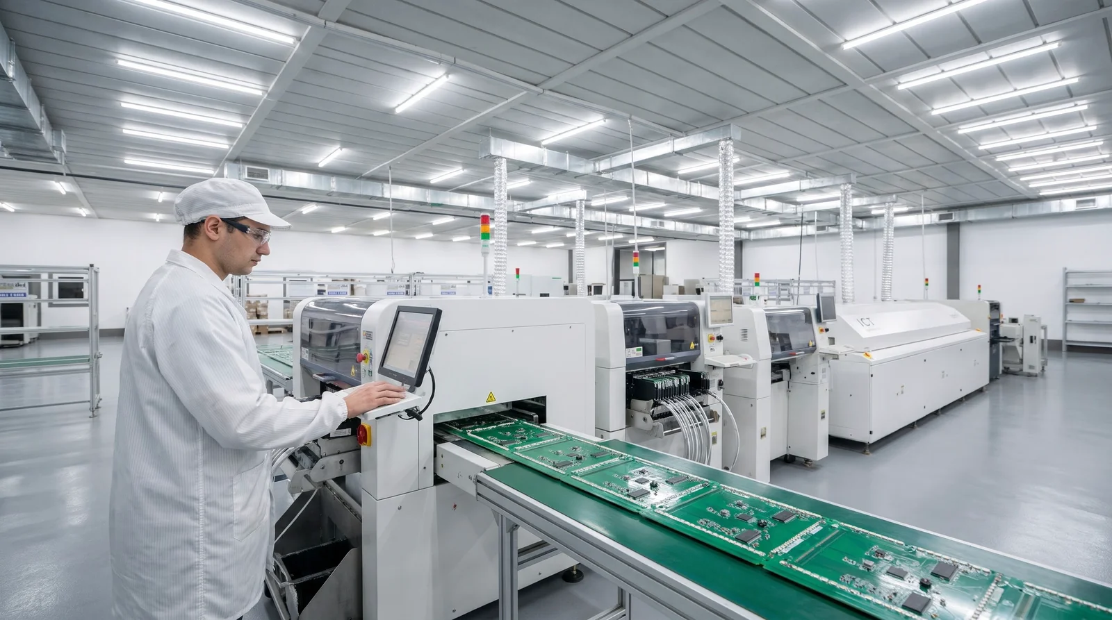
Cycle time is where LED projects are won or lost commercially, because LED boards are often built in high volume and the placement count per panel is high. The temptation is to select on the datasheet CPH, but the datasheet rate is measured under ideal conditions — a single component type, a short board, no lens handling — and the real LED rate is lower. Evaluating cycle time properly means counting the real placements, accounting for the lens and height constraints, and confirming that the machine's real rate meets the volume across the full panel, not just at its centre.
This chapter examines throughput for LED boards. It covers how to count real cycle time for an LED panel, how placement count and head selection interact, how to balance throughput against the lens and height constraints, and how much headroom to plan for changeovers. It closes with a comparison of machine classes by throughput role. Getting this axis right is what makes the selected Hanwha pick and place machine for LED PCB assembly a production asset rather than a demonstration, so the chapter is deliberately concrete about how the real rate is measured.
Real cycle time starts from the panel, not the datasheet. Count the total placements on the panel — every LED, lens, driver IC, connector and passive — and divide by the machine's real placed-component rate for that mix. The real rate is lower than the quoted CPH because it includes lens handling time, nozzle changes, fiducial reads, board transfer and the small stops that a production mix incurs. On an LED panel with tall lenses and a mix of component types, the gap between quoted and real can be substantial, and it is the real rate that decides whether the machine meets the plan.
The count has to be per panel, because the panel is what the line produces. A multi-up panel multiplies the per-board count by the number of boards, and a long panel may carry hundreds or thousands of placements. Dividing the panel's total placements by the required panel takt gives the required real CPH, and comparing that to the machine's real rate gives the answer. Counting this way, rather than trusting a headline figure, is what turns cycle time from a hope into a calculation, and it is the first step of the throughput axis.
Head selection follows the placement count and the component mix. LED boards are dominated by high-count LEDs and lenses plus a smaller number of driver ICs, connectors and passives. A machine with a fast multi-nozzle head places the high-count LEDs and lenses at speed, while a flexible head handles the connectors and odd parts. The right head configuration depends on the ratio of high-count to low-count components and on how much of the panel is the same part placed many times, which is common on LED strips.
For a strongly LED-dominated panel, a fast head that places the repeated LED and lens at high rate is the priority, with the flexible head covering the remainder. For a mixed LED product with many connectors and driver ICs, the balance shifts toward flexibility. Evaluating head selection against the real placement profile — rather than accepting a standard configuration — is what keeps the machine matched to the product. The placement count per component type, taken from the BOM, is the data that drives this decision, and it should be gathered before the machine is specified.
Throughput cannot be maximised in isolation from the lens and height constraints. A machine that places LEDs fast but must slow down for tall lenses, or that needs a special nozzle and approach for each lens, will not achieve its chip-placing rate on an LED panel. The real throughput is the rate at which the machine can place the whole mix, including the parts that force a slower approach, and that is the number to evaluate. Ignoring the lens and height cost in the throughput calculation overstates the machine's capability on the real product.
The balance is found by measuring the real rate on a panel that includes the tallest and most awkward parts, not on a simplified test board. A machine such as the DECAN F2 economical SMT placement machine can be a strong throughput choice for LED work when its head and nozzle set match the lens and height profile; the same machine can underperform if the profile forces it to slow down. Matching the throughput claim to the real mix is what makes the cycle-time evaluation honest, and it is where the lens axis and the throughput axis meet.
Throughput planning should include headroom, because LED production rarely runs one product forever. A machine planned exactly to takt leaves no room for a heavier panel, a slower lens or a changeover, and any of those pushes the line behind. Planning the machine to run somewhat above the required rate — a margin of ten to twenty-five percent is a common rule — gives the line room to absorb variation without missing commitments. The margin is not waste; it is the buffer that keeps a high-volume LED line on schedule when the product mix shifts.
Changeover is the other half of headroom. LED lines often run several products, and each changeover costs time that the throughput plan must absorb. A machine whose feeder and nozzle setup changes quickly, and whose program can be loaded without a long setup, effectively has more usable throughput than one that stalls at every product change. Evaluating throughput together with changeover speed, and planning headroom for both, is what keeps the real output close to the plan. The table below summarises machine classes by their throughput role on LED work as a rough guide.
Machine class | Throughput role | Best for |
|---|---|---|
Flagship multi-head | Highest placement rate | High-volume LED strips, dense panels |
Value throughput | Balanced rate and cost | Mid-volume LED, mixed panels |
Cost-effective single-head | Moderate rate, low entry | Lower-volume LED, varied products |
Flexible multi-function | Handles odd parts slower | Connectors, driver ICs, lenses |
Used as a starting point, the table helps match the machine class to the volume and panel, but the real decision still depends on the measured rate for the actual mix. A class that looks right on the table can be wrong for a panel with many tall lenses or a long changeover list, and the measured rate is what settles it. The throughput axis is closed only when the real rate, measured on the real panel, meets the plan with headroom for changeover.
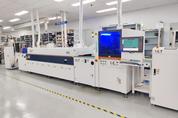
A placement machine does not make an LED board alone, and the sixth axis is the one that treats the machine as part of a line rather than as an island. The LED process has its own requirements downstream — a reflow profile that suits a long thin panel and tall optics, a conveyor that carries the long board without misalignment, an inspection step that catches the LED-specific defect set, and a material flow that keeps feeders and lenses supplied. A machine selected without regard to the line can be a good machine in a line that cannot support it.
This chapter examines full-line support for LED assembly. It covers the reflow and thermal profile considerations for long LED panels, the conveyor and line interface that carry the board, the inspection approach and the LED-specific defects to watch for, and the feeder and material flow that keep the line running. It is the chapter that turns a machine selection into a line selection, and it completes the six-axis evaluation of Hanwha pick and place machine for LED PCB assembly equipment before the guide closes with a consolidated checklist.
Reflow is where a long thin LED panel is most at risk. The thermal profile has to heat the panel evenly enough that it does not warp beyond the tolerance for the tall optical components, and it has to stay within the LED's thermal limits so the light output and lifetime are not degraded. A profile that suits a small rigid board can overheat the ends of a long panel or leave the middle cool, and a panel that warps during reflow can lift or skew the lenses that were placed accurately. Reflow is therefore not a separate process to be sorted out later; it is part of what the placement machine has to feed into.
The evaluation item is to confirm that the machine's output — panel size, component height, placement accuracy — can be carried through the available reflow without losing flatness or damaging the optics. That may mean a reflow with multi-zone control and panel support, and it may mean a panel design that tolerates the profile. Checking the reflow alongside the placement machine, rather than assuming any reflow will do, is what keeps the line coherent. The LED product's thermal sensitivity makes this check more important than on a standard board, where reflow is more forgiving.
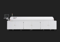
The conveyor is the physical link between machines, and for LED work its length and support matter. A long LED panel has to travel from the placement machine to the reflow and inspection without sagging or misaligning, and the conveyor has to support it along its span. The line interface standard — commonly SMEMA for SMT lines — determines how machines hand boards to each other, and a machine that does not follow the line's interface convention creates integration friction. Confirming the conveyor length, support and interface before the machine is ordered prevents a line that cannot actually move the board.
The interface also governs how the line behaves as a system. A machine that signals board-ready and board-complete correctly lets the line run without manual intervention, and one that does not creates stops and misloads. For an LED line, where the panel is long and the process is high-volume, the interface has to be reliable enough to run unattended between changeovers. Evaluating the conveyor and interface as part of the machine selection, rather than as an afterthought, is what makes the line work as a line rather than a set of machines that happen to be near each other.
Inspection for LED boards has to catch the defects that LED work produces, which differ from a standard board's. Lens misalignment and tilt, LED polarity errors, missing or damaged lenses, and the placement-height errors that come from a warped panel are all LED-specific, and an inspection step designed for chips and ICs may not catch them. AOI can check placement and polarity, but the optical consequence of a slightly rotated lens may only show up in a functional light test, so the inspection approach has to combine placement inspection with a light-output check where the product demands it.
The evaluation item is to confirm that the inspection step can catch the LED defects at the rate the line produces. That may mean an AOI configured for lens inspection, a functional light test, or both, and it has to be matched to the placement machine's output. Inspection that is too slow bottlenecks the line; inspection that misses lens defects lets them reach the customer. Selecting the inspection alongside the placement machine, and confirming it covers the LED defect set, is part of full-line support rather than a downstream detail.
The line also has to be fed. LED panels consume LEDs, lenses and passives at high rate, and the feeder bank, the lens trays and the material flow have to keep up without stopping the line. A machine that places fast but runs out of a reel or a tray every twenty minutes is not a fast line. The feeder and material plan — how many feeders, how the lenses are presented, how reels and trays are replenished — is part of the full-line evaluation, and it is where the flexible SMT line planning guide becomes relevant even for a high-volume LED line, because changeovers and material flow still shape throughput.
For LED work there is also a machine choice that reflects the product's dominance by repeated placements: a high-speed LED chip shooter, such as the I.C.T LED SMT chip shooter, is designed around the repeated LED placement that LED strips demand, and it can be the right throughput engine for the line even when a more general mounter handles the rest. Matching the machine set to the LED placement profile — a shooter for the repeated LEDs, a flexible machine for the rest — is the full-line version of the head-selection decision, and it is where the six axes come together into a line that actually produces.
The six axes are only useful if they are consolidated into a single evaluation that can be compared across candidate machines and then verified on acceptance. This chapter does that consolidation. It shows how to build an evaluation matrix that scores each candidate against the six axes for your real LED panel, how to run a trial that proves the machine on that panel rather than on a test board, how to accept and sign off the machine against the evaluation, and how to keep the evaluation honest as the LED product range changes.
The checklist is deliberately practical: each axis becomes a line item with a measurable criterion, so the comparison is evidence-based rather than impressionistic. This is the chapter that turns the preceding analysis into a decision and then into a verified acceptance, and it is the natural close of Hanwha pick and place machine for LED PCB assembly selection. A machine that clears this checklist on your real panel is a machine you can commit capital to with confidence, because every axis has been checked against the product rather than against a brochure.
The evaluation matrix is a table with one row per machine and one column per axis, each cell carrying a measurable criterion and a pass, marginal or fail judgement. Envelope is a length in millimetres against the longest panel; lens and height is a nozzle clearance and accuracy against the tallest and finest-pitch optics; support is a maximum deflection at the placement area; cycle time is a real placed-component rate against the panel takt; line support is conveyor length, interface standard and reflow compatibility. Filling the matrix for each candidate makes the comparison explicit and exposes the trade-offs a single number would hide.
The matrix also forces the criteria to be set before the machines are seen, which prevents a persuasive demonstration from shifting the goalposts. If the envelope criterion is the longest panel and a candidate cannot meet it, that is a fail regardless of how well it performs on a shorter board. Building the matrix first, with the criteria derived from the real product, is what keeps the evaluation honest and comparable. It is the same evidence-based approach used throughout this series, applied to the LED case where the axes happen to be length, optics, height, support, speed and line.
A trial is where the matrix meets reality. The trial should run the actual LED panel — or a representative one with the same length, thickness, lens profile and placement mix — through the candidate machine, and measure the six axes on that panel rather than on a simplified test board. Envelope and support are confirmed by running the full-length panel; lens and height by placing the tallest optics; accuracy by measuring across the panel's length; cycle time by timing the real mix; line support by confirming the output feeds the available reflow and inspection. A trial on a short, flat, chip-only board proves very little about LED capability.
The trial should also stress the marginal cases: the longest panel, the tallest lens, the finest pitch, the densest region. These are where a machine that looks good on the average will fail, and they are exactly the conditions the production line will meet. Measuring placement performance against IPC-9850 where the acceptance uses that standard, and recording the results against the matrix criteria, makes the trial a verification rather than a demonstration. A machine that passes the trial on the real panel, including its worst cases, has earned the place on the line.
Acceptance turns a successful trial into a controlled asset. It records the machine configuration, the evaluated criteria and the trial results as the approved baseline, together with the acceptance tests that will be repeated at installation. For LED work, acceptance should include the envelope, lens and height checks, the support and flatness check, and a cycle-time confirmation on the real panel, so that the machine is accepted against the product it will build. The SMT machine acceptance and sign-off checklist provides the structure, with the LED axes added to the standard machine checks.
Sign-off should be specific enough that a later engineer can reconstruct what was accepted and why. That means recording the panel used, the criteria, the results and any agreed exceptions, and keeping it with the machine. An acceptance that says only "machine performs to specification" is not useful when the LED product changes and the line needs to know what was actually verified. A specific, evidence-based acceptance is what protects the investment and gives the production team a baseline to maintain against.
LED product ranges change, and an evaluation that was right for one panel may not hold for the next. A longer panel, a taller lens, a denser layout or a new driver IC can each move one of the six axes beyond what was accepted, and the machine that was suitable last year may be marginal this year. Keeping the evaluation honest means re-checking the axes when the product changes, and treating a new LED product as a reason to revisit the matrix rather than to assume the machine still fits.
The practical routine is to re-run the relevant axis checks for any new panel or lens, and to confirm the support and conveyor still suit the new lengths. This is the same discipline as keeping a feeder and nozzle selection valid as the BOM changes, applied to the machine-level evaluation. Done this way, the evaluation does not decay into a one-time purchase justification; it stays a living check that the equipment still matches the product, which is what keeps an LED line capable as the product family grows.
Evaluate the machine against your LED panel, not the brochure
Choosing equipment for LED PCB assembly is not a speed contest; it is a matching exercise across six axes that general-purpose selection tends to underweight — long-board envelope and handling, LED lens geometry, component height and clearance, board support and warpage, real cycle time on the actual panel, and full-line support from reflow to inspection. A machine that clears all six on your real LED panel will build the product at the yield and rate the project needs, while a machine that clears five and is marginal on the sixth will build it with a problem you already know about. The practical next step is to take your longest, thinnest, most lens-heavy panel and run it through the evaluation matrix: confirm the envelope and support, check the lens and height handling, measure the real placed-component rate, and verify the line interface. That evidence, gathered before the order, is what separates a confident LED equipment decision from an expensive experiment. Start from the Hanwha pick and place equipment lineup and evaluate each candidate against the panel you actually build.
There is no single factor, but if one has to be named first it is board envelope and handling, because a machine that cannot carry your longest LED panel cannot place it at all, regardless of its other strengths. After envelope, the lens and component-height axis is usually the next most decisive, because LED optics impose handling and accuracy requirements that a general-purpose selection misses. The honest answer is that all six axes matter and the binding one is whichever your particular panel stresses most — which is why the evaluation should be run on your real product rather than a generic example.
Often yes, but with caveats that depend on the panel. A standard mounter may handle a moderate LED board well if its envelope covers the length, its support keeps the panel flat, its nozzle set suits the lenses and its real cycle time meets the volume. Where it typically falls short is on very long panels that exceed its envelope, on thin panels that warp without better support, and on tall lenses that strain its nozzle clearance. The point of the six-axis evaluation is to find out which of those applies to your product before you commit, rather than after installation.
Use a lens-specific nozzle that grips the lens body without touching the optical surface, and a feeder that presents the lens without damage — often a tray feeder for domed lenses or a specialised tape feeder for flat ones. Confirm the nozzle clearance and head travel can place the lens between tall neighbours without collision, and set the placement force so the lens seats without being pressed. Because the lens affects the light output, also confirm rotational accuracy is tight enough for the optics. These are the concrete steps behind the lens and component-height axis, and they should be verified on the real panel in the trial.
Because LED panels are long and often thin, so they flex under their own weight and under the placement force. If the panel is not held flat at the placement point, the nozzle meets the board at the wrong height and the accuracy the machine is capable of never reaches the board; the error also varies along the length, so the far end of a long panel can be worse than the near end. Support has to reach the middle of the panel, not just its edges, and it has to keep the panel flat through reflow as well. Support is therefore a precondition for accuracy, not an accessory.
Count the total placements on the panel — every LED, lens, driver IC, connector and passive — and divide by the machine's real placed-component rate for that mix. The real rate is lower than the quoted CPH because it includes lens handling, nozzle changes, fiducial reads, board transfer and small stops. A multi-up panel multiplies the per-board count by the number of boards. Dividing the panel's total placements by the required panel takt gives the required real CPH, and comparing that to the machine's real rate tells you whether it meets the plan. Always use the real rate, not the datasheet number.
It depends on the placement profile. If the panel is dominated by the same LED placed many times at high volume, a dedicated LED chip shooter can be the most efficient throughput engine, with a more flexible machine handling the lenses, driver ICs and connectors. If the product is mixed or lower volume, a general mounter with the right nozzle and support configuration may be sufficient. The decision follows the placement count per component type and the volume, not a preference for one machine class, and it is best made by measuring the real rate on the actual panel for both options.
Acceptance should include the envelope check on the longest panel, the lens and component-height check on the tallest and finest-pitch optics, the support and flatness check at the placement area, and a cycle-time confirmation on the real panel. Add the line-interface and reflow-compatibility checks, and record the panel used, the criteria and the results. The standard machine acceptance structure applies, with the LED axes added, because a generic acceptance that ignores length, optics and support does not prove the machine can build the LED product. Keep the record with the machine so it can be maintained and revisited as the product changes.
Re-check the six axes whenever the product changes — a longer panel, a taller lens, a denser layout or a new driver IC. Confirm the envelope still covers the new lengths, the support still holds the new panel flat, the nozzle and feeder still suit the new optics, and the real cycle time still meets the new volume. Treat a new LED product as a reason to revisit the evaluation matrix rather than to assume the machine still fits. Done routinely, the evaluation stays a living check that the equipment matches the product, which is what keeps an LED line capable as the family grows.