English
Views: 0 Author: Vinci Zhang Publish Time: 2026-10-27 Origin: Site


Every SMT line eventually reaches the point where manual visual inspection stops scaling. Boards get denser, components get smaller, and the defect types that matter most — the ones hiding under a BGA or inside a cold joint — stop being visible to the naked eye. That is the moment most manufacturers start looking at SMT inspection equipment, and it is also where the easiest mistake appears: buying a machine before defining the problem. The market offers solder paste inspection, pre- and post-reflow AOI, X-ray, electrical test and first article inspection, and each answers a different question. A practical way to start is to study how SMT inspection equipment is deployed across real lines — where each technology sits, what it catches, and what it cannot see — before mapping that back to your own defect list. This guide works through that framework: defect risk first, process position second, board and throughput constraints third, budget last.

SMT inspection is not one machine. It is a family of technologies that each look at the board at a different moment, using different physics. Solder paste inspection measures the deposit right after printing. Pre-reflow AOI verifies that every part landed correctly before the solder melts. Post-reflow AOI judges the finished joint. X-ray sees through the package to the joints underneath. Electrical test confirms that the network conducts and component values are correct. First article inspection locks down the setup at the start of every job and changeover.
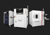
None of these replaces another. An AOI cannot see inside a BGA. An X-ray cannot confirm polarity. An ICT tester will not tell you a joint is grainy. The line works because the technologies overlap in coverage, and the selection task is deciding which overlap your product actually needs. Browsing the vision inspection equipment category as a whole, rather than one product family at a time, keeps that comparison honest.
The most common failure in inspection equipment selection is treating it as a purchasing decision with a price tag. Teams compare camera resolutions and software licenses, sign for the biggest budget they can get, and discover six months later that the machine sits idle because it was pointed at the wrong process step. Selection done properly starts one level up: what is your line's actual defect profile, and where is each defect created and detectable?
That reframing changes the questions you ask a supplier. Instead of "how accurate is your AOI," the question becomes "which of our defect types can this station catch before rework, and which will still escape." A modest machine at the right process step always outperforms a flagship machine at the wrong one — and equipment matched to a documented defect list keeps its value as the product mix changes.
This guide follows a five-layer framework. First, classify your defect risk: what can go wrong, where it originates, and whether it is visible. Second, map each defect family to the method that can catch it at the process position where detection is still cheap. Third, check the constraints your boards impose: sizes, component types, double-sided flow, industry requirements. Fourth, verify that inspection cycle time fits your takt and that the configuration matches your volume. Fifth, weigh budget, false call rates and total cost of ownership.
Each layer narrows the field, and by the budget conversation the shortlist should already be down to one or two credible configurations per station. If budget comes first, the process runs backwards and usually ends with equipment that demos well and underperforms on the floor.

Before any supplier conversation, write down the defect types your product can realistically produce and sort them into two buckets: visible and hidden. Visible defects — missing components, misalignment, reversed polarity, wrong value on a marked package, solder bridges, insufficient or excess solder — are the natural territory of optical inspection. Hidden defects — voids under a BGA, insufficient solder on a leadless package, an internal open in a passive — need X-ray, electrical test or functional verification.
This single sorting exercise eliminates most bad purchases. If your boards have no area-array packages and no hidden joints, a post-reflow AOI plus electrical test may cover everything that matters. If your product is dominated by BGA and QFN devices, optics alone leave your biggest risk untouched and X-ray moves from optional to structural. The way you match SMT inspection methods to defect risks determines everything downstream, so it deserves real data rather than assumptions.
Optical methods are powerful but bounded by line of sight. A post-reflow AOI judges a joint by its shape, brightness and surrounding geometry from above, which works well for gull-wing and chip terminations and fails for anything the package hides. Under a BGA, the solder balls are simply not there to be photographed — the collapse, the voids and the bridging happen in a space the camera cannot enter.
That is why X-ray and AXI exist. They trade speed and cost for the ability to see the joint itself, and they pay for themselves exactly on the products where hidden joints dominate the risk. The practical rule: if a defect can escape as a field failure without a visible symptom, it must be covered by something other than optics. Boards that mix both worlds usually end up with optical coverage for the whole board plus targeted or sampled X-ray for the array devices.
The most underused input in equipment selection is the data you already have. Pull the last few months of AOI results, rework logs, electrical test failures and customer returns, and rank defect types by frequency and by cost. Frequency tells you where inspection earns its keep every day. Cost tells you which single escape would hurt most. A rare defect that triggers a field return in a safety-relevant product outranks a common defect that is reworkable in-house.
That list becomes your requirement document. Every candidate machine is then evaluated against the list, not against a feature sheet — and after installation, the same list is the scoreboard that proves whether the equipment reduced escapes and rework or just moved the workload. Suppliers respond well to this approach too, because a requirement document turns a demo into a measurable test.
New lines and new products do not come with defect history. In that case, start from the assembly's structure. Fine-pitch and area-array content pushes X-ray onto the list. High mix and frequent changeovers push first article inspection and fast programming to the top. Stable high volume justifies inline automation. Automotive, medical and industrial products tighten documentation, traceability and validation expectations even where the same board would pass in consumer electronics.
Write these assumptions down and treat them as hypotheses to be corrected by your first months of production. The point is not to be perfectly right at the start — it is to avoid the opposite failure, where no assumptions are written at all and selection drifts toward whatever the last supplier demo happened to show.

Solder paste inspection sits immediately after printing, and it is the earliest point where a measurable signal exists. Printing generates most solder-related defects — insufficient paste, excess paste, slump, fine-pitch bridging, deposit misalignment — and every one is far cheaper to correct while the board is still clean and unpopulated. Once parts are placed and reflowed, the same defects become solder balls, bridges and unreliable joints that need touch-up or scrap.
A 3D solder paste inspection machine measures the height, area and volume of each deposit and feeds that data straight back into the printing process. On lines running fine-pitch or array content, SPI is usually the highest-leverage single station: it prevents defect classes rather than detecting them after the fact, and its SPC output shortens the loop between a printing drift and the correction that stops it.
Pre-reflow AOI inspects the board after placement but before the solder melts. Its job is not solder quality — the joints do not exist yet — but placement integrity: missing components, misalignment and skew, reversed polarity, wrong package or feeder, lifted leads and damaged parts. Because the solder has not reflowed, every defect it finds is fully correctable: the part can be removed, replaced and re-inspected without touching a finished joint.
This position earns its keep on lines with high component density, polarized devices such as diodes, electrolytic capacitors and connectors, and any product where a single reversed part can destroy a board at power-on. It also reduces the burden on post-reflow inspection, because placement-related escapes are removed before they become solder-related rework.
Post-reflow AOI is the station most people mean when they say "AOI." After reflow, it judges the finished assembly: solder bridges, insufficient or excess solder, cold and disturbed joints, tombstoning, missing or misaligned parts, foreign material and surface contamination. On many lines it is the last automated gate before electrical test, and its output is the acceptance decision against the visual criteria your product requires.
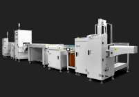
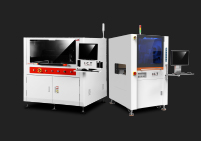
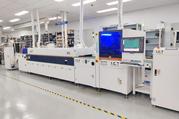
Coverage depends on how well the joint is exposed. Gull-wing leads, chip terminations and connector pins are straightforward; area-array packages are not, and that boundary belongs in your selection criteria rather than being discovered later. For most SMT lines the station is an online AOI machine in the conveyor flow, and the broader family of AOI inspection solutions also covers DIP and coating processes. Acceptance criteria are typically aligned with industry references such as IPC-A-610, which defines acceptability classes for electronic assemblies.
When the risk is inside the package, X-ray is the method that sees it. A BGA's solder balls, the terminations of a leadless QFN, the internal construction of a connector or the hidden fillet on a press-fit part are invisible to cameras and visible to X-ray. The station inspects the joint itself: ball presence and alignment, bridging between balls, voiding within the joint, and sufficient solder where no camera can reach.
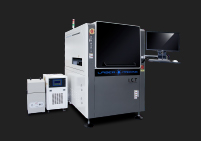
The trade-offs are speed and cost. X-ray is slower per board than optical inspection and the equipment is more expensive, so it is normally applied selectively — on boards known to carry hidden-joint risk, on sampled boards from each lot, or inline where a single BGA escape would be unacceptable. The decision is a risk decision, not a technology preference: if your defect list says the failure mode is under the package, an X-ray inspection machine is not a luxury, and skipping it is the actual risk.
Optical and X-ray inspection judge the assembly's structure. Electrical test judges its function: does each network conduct, is each component within tolerance, are the power rails isolated, do the digital interfaces respond. An ICT tester applies signals through fixtures or probes and compares measured values against the expected values from the CAD data. It catches what no camera sees — wrong-value components, opens inside passives, shorts under the package, manufacturing damage to a trace.
The choice between fixture-based ICT and flying probe comes down to volume and mix. ICT with a dedicated fixture is fast and repeatable, and the fixture cost is easily justified at stable, high volume. Flying probe needs no fixture and adapts through software, which makes it the natural fit for high-mix, low-volume production and frequent design revisions. Neither replaces optical inspection — they answer different questions — but every complete line has some form of electrical verification in it.
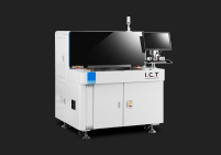
Automated stations inspect every board the same way. The risk they cannot cover is the wrong setup: a feeder loaded with the wrong reel, a stencil swapped for a similar board, a program written for the previous revision. First article inspection closes that gap. A first article inspection machine verifies the first board of every job against the BOM and CAD data — part values, polarities, positions and labels — before the rest of the lot runs.
On high-mix lines with frequent changeovers, this station often prevents more escapes per dollar than any other single investment, because the failure mode it covers — a correct machine running an incorrect setup — is the one automated inspection is blind to by design. Visual stations staffed by trained operators still have a role at final assembly and for subjective criteria, but they should add judgment, not duplicate a machine's work.

The physical envelope of your boards is a hard constraint that eliminates machines before any technical comparison starts. Conveyor width, board length and thickness range, edge clearance and support requirements all have to match the equipment's handling capability. Thin boards and large panels bring their own problems: they sag under their own weight, they warp during reflow, and they need adequate support inside the station or the same warp that causes solder defects will also cause focus failures and false calls.
Board handling also interacts with the rest of the line. If your boards pass through a specific conveyor height and direction upstream, the inspection station has to accept the same flow, or you are buying a buffer and a lift as well. Confirm the handling envelope against your largest and smallest boards, with the thinnest panel included, before shortlisting anything.
Component mix drives detection capability more than any other single factor. Very small chip components are routine for post-reflow AOI. Fine-pitch packages push camera resolution and lighting requirements up and make pre-reflow placement verification more valuable. Area-array devices — BGA, QFN, LGA — shift part of the risk to X-ray. Tall components, connectors and heatsinks cast shadows and block camera access, which affects lighting design and sometimes forces a second viewing angle.
Write your component inventory as ranges, not as one typical board: smallest passive size, finest pitch, largest array package, tallest component, and the presence of polarized or optically confusing parts. That range is what a supplier needs to propose a configuration that still works when your next product arrives — and it protects you from equipment perfectly matched to today's board and nothing else.
If your product is assembled on both sides, the inspection plan has to account for the second pass. Boards that have already been through reflow once carry populated components on the bottom side, which constrains conveyor support, changes what a top-side camera can see, and requires clearance for parts that now protrude. Some configurations handle this with inverted cameras, dual-side AOI or a turnover unit; others cannot take the board back through after second-side reflow without damage.
Flow direction matters too. Where does the board go after inspection — straight to the next station, into a buffer, or out to rework? The NG/OK routing, buffer capacity and rework loop all belong in the layout conversation, because a station without a clean exit path becomes a bottleneck within weeks. These questions link directly to how you plan station positions, covered in the layout planning article in this series.
The same board can be a consumer product in one factory and a safety-relevant assembly in another, and the inspection plan should not be identical. Automotive, medical, industrial control and power electronics typically demand more complete documentation, tighter traceability, validated and locked programs, and defined rework and verification rules. These requirements influence selection through the software rather than the optics: report formats, audit trails, user access levels, program version control and data retention all become criteria.
None of this means buying the most expensive station. It means matching the station's data and process-control capabilities to the documentation your customers and auditors will ask for. Ask early what reports your biggest customer expects to see, because that answer often narrows the supplier list faster than any technical specification.

Every inspection station has a cycle time, and that number has to fit inside the takt your line already runs. The calculation is simple but frequently skipped: take the slowest station in the line, add the inspection cycle, and check whether the combined time still meets the required output. If it does not, the line does not get faster by adding the station — it gets slower, and the pressure that creates shows up later as boards routed around the inspection station, which defeats the purpose of buying it.
Ask suppliers for cycle time on boards like yours, with your component density, not a best-case number from a light demo board. Where the honest cycle time does not fit, the usual answers are a faster configuration, partial inspection of the board area, sampling by rule, or moving the station offline with buffered batches — each with trade-offs that belong in the decision, not in a footnote.
The inline versus offline decision is really a decision about volume and flexibility. Inline inspection sits in the conveyor flow, inspects every board automatically, and returns the board to the line or diverts it to rework without an operator touching it. It is the right answer when volume is stable, the mix is narrow and the cost of a missed defect is high — the automation pays for itself in labor saved and escapes prevented.
Offline inspection decouples the station from the line: boards come to the machine in batches, brought by an operator or a robot. It fits lower volume, high mix, frequent changeovers, and lines where a full inline station cannot be justified by takt. An offline AOI machine can also serve as a shared resource across several lines or as a verification station for reworked boards. Many factories end up with a hybrid: inline coverage for the high-runners, offline capacity for everything else.
Inspection equipment does not exist in isolation — it exists inside a material flow. Every station needs a defined answer to three questions: where does a good board go, where does a bad board go, and what happens when the next station is not ready to receive. Without buffer capacity between stations, a single stoppage propagates upstream and the inspection station becomes the constraint. Without a clean NG exit, failed boards accumulate, get mixed with good ones, or get quietly reintroduced to the line.
Design the flow before buying the machine. Mark the OK path, the NG path, the rework loop and the buffer on the layout, and confirm the station's conveyor interfaces match. This is unglamorous work, and it is the difference between a line that inspects and a line that inspects while flowing.
Equipment decisions live on the floor for years, and the product mix will not stay still. A configuration that exactly matches today's volume has no room for the successful product that doubles next year, and retrofitting throughput after the fact costs more than planning for it. Where growth is plausible, prefer configurations that can be extended — additional cameras or lighting modules, a second inspection head, conveyor expansion, or software capacity that is licensed headroom rather than a hard limit.
This does not mean buying capacity you will never use. It means asking, during selection, what the upgrade path is and what it costs, so growth becomes a planned purchase instead of a replacement. Suppliers who answer that question concretely are usually the ones whose equipment is still supported five years later.
Inspection equipment is only as good as its programs, and programming effort is a real operating cost that rarely appears on a quotation. A station that takes days to program per product is a hidden labor line item on a high-mix line; a station with offline programming, automatic program generation from CAD data and good recipe libraries can bring that down to hours. Ask how programs are created, who can create them, how long a new product takes from CAD to first inspection, and what happens when the board revision changes.
Also ask about program verification. A new or edited program needs to be proven against known-good and known-bad boards before it is trusted on production. That workflow — sample boards, defect libraries, sign-off — should live in the software, not in a folder on someone's desktop.
Inspection data is worth more than the pass/fail decision it produces. Solder paste volumes, placement offsets and joint measurements trend over time, and those trends show process drift long before they produce defects. This is the difference between inspection that sorts and inspection that improves: the first catches defects, the second prevents them. Using inspection data for process feedback and quality reporting turns each station into a process sensor, and it is the mechanism through which inspection equipment pays for itself beyond rework avoidance.
When evaluating equipment, look at the data side with the same seriousness as the optics: what is measured, at what resolution, how it is trended, what alarms it raises, and how easily an engineer can get from an alarm to the root cause. A machine that produces decisions but no usable data is half a machine.
Traceability is the ability to answer, months later, which board was inspected by which program with which result. It starts with board identification — barcode, laser mark or position-based tracking — and continues through result storage, program version and operator actions. For products in regulated industries it is a requirement; for everyone else it is the cheapest insurance available, because it converts a customer complaint from an investigation into a lookup.
The requirement shapes selection in practical ways: does the station read and write board IDs, does it store results per board or per batch, how long is data retained, and can it be exported in a format your quality system accepts. Confirm this during selection, because retrofitting traceability onto equipment that was not designed for it is painful and sometimes impossible.
Modern lines do not run on islands. Inspection results, defect codes, counts and process parameters feed the manufacturing execution system, which routes boards, releases work orders and builds the quality record. Equipment that cannot talk to that system forces manual transcription, and manual transcription is where data goes to die. Confirm the interface: standard protocols, documented data formats, and a real integration path to the MES or ERP you actually run — not a promise of future support.
The same applies upstream. If your line is planned around recipe download, program selection by work order and automatic result upload, the equipment has to participate in that loop. Integration capability is therefore a selection criterion at the same level as detection capability, and on a data-driven line it is often the criterion that decides between two otherwise similar machines.
The quotation covers the machine, the software licenses and the installation. It does not cover programming labor, validation time, operator training, consumables, calibration, periodic maintenance, spare parts or the cost of the station being down while a service engineer is booked. Total cost of ownership over five years frequently changes the ranking of two candidates that looked close on price, and it is the number your finance team should be comparing.
Build the TCO model before the shortlist is finalized: purchase, installation, training, annual service and calibration, consumables, expected programming hours per year, and the residual value or upgrade path. A machine with a higher purchase price and lower operating burden can easily be the cheaper decision, and the model makes that visible instead of arguable.
A false call is a good board judged bad. It feels like the safe direction to fail, but its cost is real and recurring: rework labor on boards that were never defective, handling damage introduced by the extra pass, capacity lost to re-inspection, and — most corrosive over time — operator trust. When a station cries wolf often enough, people stop believing it, and then the real escapes start walking through.
False call rate therefore belongs in your acceptance criteria, and it should be measured on your boards, not quoted from a demo. Ask how the supplier tunes the balance between detection and false calls, what the expected rate is for products like yours, and what happens to that rate when the product mix changes. Two machines with the same detection capability and very different false call rates are not the same machine.
The other side of the ledger is the escape — a defective board that leaves the factory. Its cost includes rework or replacement, freight, the labor of the failure analysis, and in the worst case a field return, a customer line-down or a safety recall. This number is usually much larger than the entire inspection equipment budget, which is why the escape conversation matters more than the price conversation. If a single class of escape costs more than the station that would prevent it, the decision is already made.
Estimating escape cost is not always easy, but an order-of-magnitude number is enough to change the decision. Work with your quality and finance colleagues to put a plausible figure on the top three escape scenarios. That figure is what turns inspection equipment from a cost center into risk management, and it is the argument that survives budget review.
Inspection equipment sits in the middle of a production line, and when it stops, the line stops. Service responsiveness is an operating requirement, not a courtesy. Ask where the nearest service engineers are, what the response commitment is, whether remote support is available, and how spare parts are supplied to your region. On-site installation, operator training and application support during the first production months are part of the delivery, not extras.
Training deserves specific attention: operators who understand what the station measures make better decisions about what to believe, and engineers who understand the software keep programs healthy as products change. Budget the training time honestly during selection, because the station that nobody fully understands is the station that gets bypassed within a year.
Start with the document you built in section 2: the ranked defect list, the visible/hidden classification, the board envelope, the component ranges, the takt constraint and the traceability requirements. This one or two pages is the requirement specification, and every supplier response should be written against it. It does not need to be long — it needs to be specific enough that two suppliers answering it can be compared line by line.
The discipline here is refusing to skip ahead. Suppliers will offer demos and reference lists; both are useful, but neither substitutes for knowing what you need. The requirement document also protects you internally, because it makes the selection criteria visible to everyone who will later judge the purchase.
Turn the requirement document into a matrix: defect types and process positions down one side, candidate configurations across the top, coverage marked cell by cell. Gaps become visible immediately — usually in the hidden-joint row or the takt row. Add the commercial columns: cycle time on your boards, false call expectation, programming effort, data and integration capability, service footprint and TCO. The shortlist falls out of the matrix rather than out of the sales process.
Two or three candidates per station is the right depth. More than that and the comparison becomes unmanageable; fewer and you have no benchmark. Keep the matrix alive through the evaluation — it is the document you will defend the decision with.
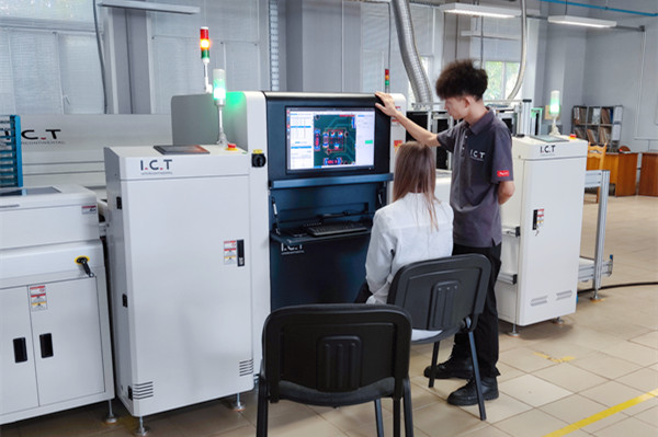
Demos with supplier sample boards prove the machine works. Only your boards prove it works on your product. Bring your highest-density board, your most awkward mechanical case, a board with known defects and a board with a marginal, borderline condition. Run them through the candidate equipment and watch two things: does it catch the defects on your list, and does it pass the boards you know are good. The second half matters as much as the first, because that is where false calls appear.
Ask to see the programming workflow during the same visit, on one of your boards, with your engineers at the keyboard. The time it actually takes is the number that will recur on every new product. A FAT and SAT checklist structures this stage so the results are recorded rather than remembered.
If the volume justifies it, run a pilot: install the candidate on a trial basis, run production boards for a defined period, and measure. The metrics are the ones from your requirement document — detection against your defect list, false call rate on known-good boards, cycle time, programming hours per new product, and the effort of getting data into your MES. A pilot converts a demo impression into evidence, and evidence is what survives the first bad week on the floor.
Not every purchase justifies a full pilot, and smaller lines can substitute a structured on-site test with their own boards and defect samples. The principle is the same: judge the equipment on your product, over enough boards to see the false call behavior, not on the supplier's showcase.
When the evidence is in, the decision usually makes itself — and when it does not, the gap is almost always a criterion that was never written down. Go back to the requirement document, add the missing criterion, and re-score. The final decision should be defensible in one page: here is our defect list, here is the coverage each configuration provides, here is the measured performance, here is the cost, and here is why the winner wins.
Write that page down even if nobody asks for it. Six months later, when someone proposes changing the configuration or adding a station, that page is the baseline the whole conversation starts from — and it is the fastest way to keep the line's inspection strategy coherent as products and people change.
What is my defect list? Every other decision — which technology, which process position, inline or offline, which supplier — follows from knowing which defects you must catch, where they originate, and whether they are visible. Selection without a defect list is shopping, and it usually ends with a machine that is impressive in isolation and misaligned with the line.
They cover different failure points. SPI measures the paste deposit before anything is placed and prevents solder defects at the source; AOI judges the finished assembly after reflow and catches placement and joint defects. Lines with fine-pitch or array content normally need both, because SPI prevents defect classes that post-reflow AOI can only detect after rework becomes necessary.
Volume and flexibility. Inline suits stable volume, narrow mix and high escape cost, because every board is inspected automatically without operator handling. Offline suits lower volume, high mix and frequent changeovers, and can serve several lines as a shared station. Many factories run a hybrid, with inline coverage for high-runners and offline capacity for the rest.
No. AOI sees the board from above and cannot see the solder joints hidden under an area-array package. Where BGA or QFN content creates hidden-joint risk, X-ray or AXI is the method that covers it, and the usual configuration is optical coverage for the whole board plus targeted or sampled X-ray for the array devices.
It depends on the software and the board, which is why you should measure it on your own product during evaluation rather than accept a general answer. Stations with offline programming and CAD-based program generation can bring a new product down to hours, while manual programming can take days per product — a difference that becomes a permanent labor cost on a high-mix line.
Your own boards through the candidate machine, including known-good, known-bad and marginal boards, with the programming workflow running in front of your engineers. Watch detection against your defect list and false calls on good boards, and record the results against your requirement document. The demonstration that survives is the one measured on your product, not the supplier's showcase.
Inspection strategy is a line-level decision, and it works best when the stations are planned together rather than bought one at a time. I.C.T supplies the complete inspection range for an SMT line — SPI, pre- and post-reflow AOI, X-ray, ICT and first article inspection — and integrates it with the printers, placement machines and reflow ovens around it, with MES and ERP connectivity and overseas engineers for installation and training. If you are building or upgrading an inspection plan, our engineers can review your defect list and line layout and propose a configuration that fits your takt, your product mix and your budget. Talk to an I.C.T engineer to start the conversation.