English
Views: 0 Author: Vinci Zhang Publish Time: 2026-11-16 Origin: Site


Choosing the process route for a new electronics assembly plant is the decision that every later decision hangs from, because the route fixes which product families you can build, how much manual labour the floor will need, what the line must be protected against, and how far the plant can grow without a second round of construction. A turnkey PCBA factory solution is often presented as a list of machines, but the machines are only the expression of a route that should have been settled first from the product itself. This guide compares the three practical routes — SMT-only, SMT plus THT, and SMT plus THT plus conformal coating — and gives you a product-led way to decide which one fits, without drifting into the separate question of which individual SMT machine to buy.

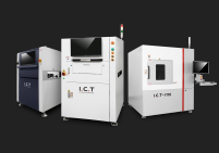
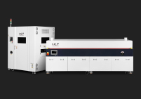
Before any layout is drawn or any quotation is compared, the route has to be fixed, because it determines the shape of the building, the utilities that must be installed, and the skills the plant must hire. A route is not a machine list; it is a statement of which assembly technologies will physically happen under this roof and in what order. Get it wrong and no amount of good equipment selection will rescue the project, since a line configured for the wrong technology either cannot place the parts you build or pays for stations you never use. The full range of configurable lines is easier to judge once you look across the complete production line category, where SMT, DIP and coating lines are shown as distinct building blocks rather than as a single fixed package.
At factory scale a process route is the ordered chain of technologies a board passes through, from bare PCB input to packed finished assembly, and it includes the joining methods, the inspection points, and any protective treatment applied along the way. It is deliberately a higher-level concept than a line configuration: two factories may both run the same route yet configure their machines differently, because the route says what must happen while the configuration says with which equipment. Confusing the two is the most common early error, because buyers compare printer and placer specifications before agreeing whether through-hole or coating belongs in the plant at all. Fix the route first, in terms of technologies and sequence, and the equipment conversation becomes a bounded, comparable exercise afterwards.
A faster placer or a better oven improves a line that is already pointed at the right product, but it cannot make a plant capable of a product family its route excludes. If the board needs through-hole connectors and the plant has no insertion and soldering stage, no placement accuracy figure closes that gap; if the product serves a damp or chemically exposed environment and there is no coating process, no amount of inspection upstream substitutes for the missing protection. Route selection therefore outranks machine selection in the strict sense that it is a prerequisite: it defines the set of machines that are even relevant to the discussion. Reverse the order and the project tends to accumulate impressive but mismatched assets, because each machine is justified on its own merits while the chain as a whole never quite fits the product.
The three routes form a ladder of capability and, equally, a ladder of complexity. SMT-only handles surface-mount assemblies where every component is placed and reflow soldered; adding THT brings insertion and a separate soldering stage for through-hole parts; adding coating brings a protective process with its own masking, curing and inspection demands. Each step up widens the range of products the plant can accept but also adds stations, utilities, floor area, labour and process control. The right route is the simplest one that covers the current product mix plus a reasoned margin for the roadmap, not the most capable one available — because capability that is never used is still paid for in footprint, capital and management attention.

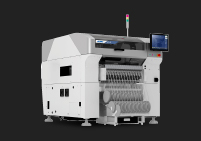
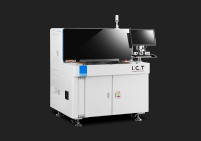
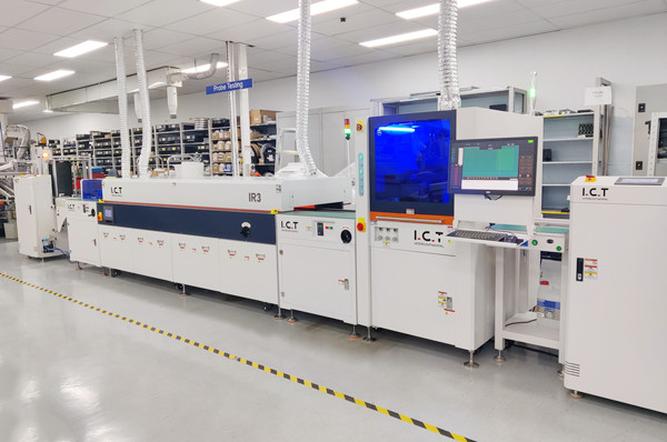
An SMT-only route is the cleanest and typically the fastest to stabilise, because it is a single continuous flow with one joining process and a short chain of handoffs. It suits a defined class of products extremely well and it fails quietly outside that class, which is why the decision deserves an honest look at the component mix rather than an assumption that through-hole can be ignored. The high-speed JUKI SMT line illustrates what a mature surface-mount flow looks like when it is configured as a coherent chain, but the route question here is whether a surface-mount-only chain is enough for your boards in the first place.
An SMT-only line places and reflow solders surface-mount devices, which today covers the large majority of active and passive components including fine-pitch integrated circuits, chip passives and most LEDs. What it does not do is insert components with leads that pass through the board and are soldered on the opposite side, so any design that relies on through-hole connectors, certain transformers, large electrolytic capacitors or mechanically loaded parts falls outside it. Some through-hole-style parts have surface-mount equivalents and can be redesigned in, but that is a product decision, not a factory decision, and it should not be assumed during line planning. Read the bill of materials for leaded parts before committing to an SMT-only route, because those parts define the boundary of what the plant can physically assemble.
The route fits products whose component population is overwhelmingly surface mount and whose mechanical loads are carried by the enclosure rather than by board-mounted parts. Consumer electronics, many communication modules, sensor boards and compact control electronics commonly sit here, because their connectors can be specified as surface-mount parts and their small size favours high-density placement. High-volume, stable-design products are especially good fits, since the route rewards repetition and the line can be tuned tightly around one or a few assemblies. Where the product family is stable and the component mix is genuinely surface mount, an SMT-only plant delivers the shortest chain, the fewest handoffs and the simplest training burden of the three routes — a real advantage that should not be given up lightly.
The limit is rarely obvious on day one; it appears when a new product arrives with a through-hole connector, a relay, or a large capacitor that the current route cannot place, and the plant must either redesign the product or send work out. High-mix operations feel this first, because variety is exactly what introduces parts outside the original assumption. A second quiet limit is mechanical: a board that will be plugged and unplugged, or that carries weight at a connector, often needs the stronger joint that a through-hole part provides, and no surface-mount pad is a perfect substitute for a lead anchored through the laminate. Designing a margin into the route — by reserving space and utilities for a future THT stage — costs little at planning time and avoids a costly retrofit later.

Adding a THT stage converts a surface-mount plant into a mixed-technology plant, and that conversion is more than placing one extra machine on the floor, because it introduces a second joining process, a second set of inspection points and a different labour profile. The DIP assembly line shows how through-hole assembly is organised as its own flow with insertion, soldering and handling steps. The route decision is whether your product mix genuinely needs that flow, and whether the value of the parts it enables justifies the complexity it adds.
Through-hole technology persists because it solves problems that surface mounting does not solve equally well. A leaded part soldered through the board forms a joint with substantial mechanical strength, which is why connectors, sockets, transformers, large capacitors and components subject to plugging forces or vibration are often specified as through-hole parts. It is also a practical choice for high-power and high-voltage parts where creepage and clearance, thermal mass, or replacement in the field favour a through-hole package. None of this makes THT "better" than SMT; it means the two technologies are complementary, and a product that mixes them needs a plant that can do both. The route question is therefore not about which technology wins but about whether your boards contain parts whose function or mechanical role calls for a through-hole joint.
A THT stage brings its own chain: component preparation, insertion — manual or machine-driven depending on volume and part geometry — a soldering process such as wave or selective soldering, and inspection of the resulting joints. It also brings material flow between the SMT and THT portions of the plant, because many boards pass through both and must be buffered, tracked and handed off without loss of identity. That handoff is a genuine process step, not an afterthought, since a board that has already accumulated surface-mount value is now moving into a second thermal and handling cycle. Planning the route means planning that interface — where boards wait, how they are identified, and how a fault in one half of the process is prevented from contaminating the other.
The added complexity pays when the through-hole content is real, stable and economically meaningful — that is, when the board genuinely needs leaded parts and the volume or the value justifies bringing their assembly in-house. A small number of through-hole parts on every board in a high-volume product can justify automation, while a large number of unique through-hole parts in a low-volume, high-mix environment may be better handled with flexible manual insertion. The decision should be made from the component mix and the volume profile together, not from a rule of thumb, because the same board can point to different answers at different volumes. What matters is that the THT stage is added for a named reason tied to named products, so its cost and its control burden are traceable to value rather than to an abstract wish to be "capable of everything."

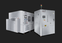
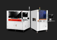
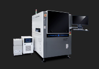
The third route adds conformal coating, a protective layer applied to the assembled board to shield it from moisture, dust, chemical exposure and electrical leakage paths. It is the route for products whose service environment is harsher than an office or a climate-controlled enclosure, and it changes the plant more than most buyers expect, because coating is a process with surface preparation, application, masking, curing and inspection requirements of its own. The selective conformal coating line illustrates how a coating stage is integrated as a controlled process rather than as a standalone booth. The decision to include coating should come from the product's environment and reliability expectation, not from a general desire to make the product "more robust."
Coating introduces questions the first two routes never ask: which areas must remain uncoated, how the board is cleaned and dried before coating, how the coating is applied to a controlled thickness, how it is cured, and how coverage is verified. Masking is often the most underestimated part, because connectors, test points, sockets and adjustable components usually must stay free of coating, and every masked feature is an operation that consumes time and materials. Coating also affects rework, since a coated board must be cleaned and recoated after a repair, and it affects inspection because the process must confirm both the presence of coating where required and its absence where forbidden. A plant that adds coating as "just another station" invariably underestimates this surrounding work.
Coating is most often specified for electronics that meet condensation, salt spray, dust, or chemically aggressive atmospheres, or that must maintain insulation resistance in humid conditions. Automotive control units, industrial controllers, outdoor communication hardware, marine and aerospace electronics, and certain medical devices commonly fall here, because their failure consequences are high and their environments are not controlled. The common thread is not the product category label but the service condition: wherever moisture or contaminants can bridge conductors or corrode joints, a properly specified coating is a normal protective measure. A route decision should start by naming those service conditions for the actual product family, since two products in the same market can have very different exposure and therefore different coating needs.
Treating coating as a process rather than a station is the difference between a line that produces repeatable protection and one that produces visible but inconsistent film. Process control means defining the coating material family, the preparation standard of the board surface, the application method and its parameters, the cure profile, and the acceptance criteria for coverage — and then holding those variables within a controlled window. Materials differ in how they are applied and removed, and in the environments they suit, so the material choice and the process choice have to be made together rather than independently. Standards bodies such as IPC publish widely used documents governing coating materials and assembly acceptability, and referencing the appropriate standard by name is a sound way to anchor a specification without inventing performance numbers. Keep the standard as a framework and let the product's real environment set the acceptance target.

The product, not the equipment catalogue, is the input that decides the route, and the practical way to read it is to build a component-mix profile from the bill of materials and the assembly drawings. This profile converts a vague sense of "we build control boards" into a concrete statement about how many parts are surface mount, how many are through-hole, what mechanical roles they play, and how these proportions vary across the product family. A turnkey JUKI PCBA production line can be configured around a known mix, but the mix must be known first; configuring the line and then discovering the mix is the expensive way round.
Start by classifying every line item in the bill of materials as surface mount, through-hole, or other, then count both the number of placements and the number of distinct part types in each class. The two counts tell different stories: a board with a few through-hole types but thousands of surface-mount placements is very different from one where through-hole parts form a large share of the assembly work despite a low count. Record which parts are inserted for function and which for mechanical strength, and flag any part whose package is unusual, large, heavy, or manually handled. This profile becomes the shared reference for the whole project — layout, utilities, staffing and inspection all trace back to it — so it is worth doing carefully and keeping updated as the product design changes.
Connectors, transformers, relays, large capacitors and similar parts deserve special attention because they are the most common reason a nominally surface-mount board still needs a THT stage. For each, ask why it is through-hole: if it is a mechanical anchor or a field-replaceable interface, the through-hole joint is probably intentional and the plant must support it; if it is a legacy choice with a surface-mount equivalent, the design team may be able to remove the need. Large and heavy parts also affect handling — they may need support during soldering, they may shadow neighbouring areas during reflow, and they may dictate board orientation on the line. Capturing these details early prevents the awkward late discovery that a handful of parts drive an entire additional process stage.
Volume and variety change the same route's economics. In a high-volume, stable-product plant, a through-hole stage can be automated to good effect and a coating stage can be tuned tightly around a narrow set of boards; in a high-mix plant, the same stages must tolerate frequent changeovers, varied masking and diverse part geometries, which favours flexible manual work and quick-change fixtures. The route itself may be identical, but its configuration, staffing and control strategy differ sharply. State your volume and mix profile alongside the component profile so that every route decision is made against both dimensions, because a route that is economical at one volume can be a burden at another even when the product design has not changed at all.
Reliability requirements are the second major input to the route, because they determine whether the product needs protection beyond the board's normal construction and how rigorously the assembly process must be controlled. This is where the third route earns its place or is ruled out. The key is to translate a reliability expectation into process terms — environmental exposure, insulation needs, expected service life — rather than into a vague instruction to "make it reliable," which no route can act on.
The stresses that normally justify coating are moisture and condensation, airborne dust and contaminants, salt in coastal or marine service, chemical vapours in industrial settings, and temperature cycling that can drive condensation into crevices. Each stress attacks a board differently: moisture and ions can create leakage paths and corrosion, dust can bridge conductors, and thermal cycling can mechanically stress joints and coatings. A board that lives in a sealed, climate-controlled enclosure may need no coating at all, while the same board mounted outdoors may need a carefully specified coating system. Naming the actual stresses the product will meet is the only reliable way to decide whether coating belongs in the route and, if it does, what kind of protection is appropriate.
Standards give the project a shared vocabulary for reliability and acceptability, and using them correctly strengthens a specification while over-claiming weakens it. Widely recognised documents from bodies such as IPC and joint IPC/JEDEC publications address assembly acceptability, soldering quality and coating material performance, and naming the relevant standard is a legitimate way to set a baseline. What a route decision should not do is quote specific acceptance limits or claim certification that has not been earned; those belong to a tested, documented quality system, not to a planning guide. Treat standards as the framework within which you will later define and verify acceptance, and let the product's environment determine how demanding that verification needs to be. This keeps the specification credible and avoids the trap of writing numbers into a plan before any process capability exists to support them.
A reliability target such as long service life in a harsh environment is a route input because it points toward protective processing and tighter control, but it is not a machine specification you can hand to a supplier. Turning it into a route means asking what the product must survive, what protection achieves that, and which processes must therefore be present and controlled. Turning it into a machine spec too early tends to produce purchases justified by a target the machine alone cannot deliver, since reliability emerges from design, materials, process and verification together. Keep the target at route level through the planning phase, then decompose it into process requirements and acceptance criteria as the plan matures, so that each control can be traced back to the exposure it addresses rather than to an abstract aspiration.
A route chosen only for today's products makes the next expansion expensive, because the plant may have no physical or data infrastructure to add a stage later. Two forward-looking considerations belong in the original route decision: traceability, which is increasingly required by customers and regulators, and expandability, which determines whether THT, coating or automation can be added without rebuilding. These are route drivers because they shape the building and the data architecture from the start, even if the corresponding machines arrive in a later phase. The discipline of planning them early is the same discipline behind a phased PCBA factory expansion plan, where capability is added in steps against reserved space and interfaces.
Designing for a second phase does not mean buying equipment you do not need; it means making sure the first phase does not block the second. Reserve floor area adjacent to the main flow for a possible THT or coating stage, keep utility capacity — power, compressed air, exhaust where coating may require it — with headroom, and avoid placing fixed infrastructure where a future line would have to go. Think in terms of process adjacency: a coating stage, for example, needs a sensible relationship to the end of assembly and to curing and inspection space, and moving it later into a cramped corner creates compromise. A modest amount of reservation at layout time is cheap insurance, because retrofit in an operating plant is always more disruptive than provision in a new one.
Traceability requirements have grown because customers increasingly expect board-level or lot-level identity to be carried through assembly and linked to process results. A route that includes multiple technologies creates more handoffs, and every handoff is a point where identity must be preserved rather than lost. That means deciding, at route level, where identifiers are created, how they are read, and how results from SMT inspection, THT soldering and any coating process are associated with the same unit. A manufacturing execution system can tie these together, but only if the process steps exist to generate the data and the layout allows the readers and stations to be placed. Planning traceability with the route avoids the common outcome of a system that is installed but only partially fed because some process steps were never instrumented.
Utilities and floor space are the physical expression of a route, and they are far cheaper to oversize at construction than to add later. An SMT-only plant has a certain power and compressed-air profile; adding THT introduces soldering extraction and additional power, and adding coating can bring exhaust, curing energy and environmental controls. Each stage also needs handling space — buffering between technologies, masking and curing areas for coating, and inspection stations at each join. When the route is fixed, list the utility and space implication of each stage, including a reasoned allowance for the next phase, and give that list to the layout and facilities designers as a formal input. This is how a route decision becomes a buildable plan rather than a concept that unravels during construction.
The framework for choosing a route is deliberately simple: settle the product and its environment first, then choose the least complex route that covers it with a justified margin, then reserve for the next stage. This keeps capital and complexity aligned with real need, and it makes the decision defensible when the project is reviewed. The framework below turns the earlier sections into a sequence you can apply to a real product family, and it connects naturally to the broader question of how to plan quality gates across whichever stages you select, because the route and the quality strategy must agree.
Four questions settle almost every route decision. First, what is the component mix — specifically, how much genuine through-hole content exists and why? Second, what is the service environment — will the board face moisture, contaminants or mechanical stress that call for protection? Third, what is the volume and mix profile — stable high volume or varied high mix? Fourth, what is the roadmap — which products are likely in two or three years, and will they need stages the current route lacks? Answer these with the bill of materials, the product specification and the roadmap in hand, and the route usually follows directly: SMT-only for clean, surface-mount-dominant products; SMT plus THT when real leaded content is present; SMT plus THT plus coating when the environment demands protection.
Seen side by side, the three routes trade coverage against complexity. SMT-only offers the shortest flow, the smallest footprint and the simplest control, but only for surface-mount-dominant products in benign environments. SMT plus THT widens product coverage to mixed-technology boards at the cost of a second joining process, insertion labour and an inter-technology handoff. SMT plus THT plus coating adds environmental protection for harsh service, at the cost of surface preparation, masking, curing, coating inspection and rework complexity. No route is universally superior; each is the correct answer for a particular product profile. The comparison should be made against your own component mix and environment rather than in the abstract, because that is where the real trade-offs become visible.
The most common mistake is choosing the most capable route as a hedge, then paying for stations that sit idle while the plant struggles to control the stages it actually uses. The second is choosing SMT-only by default because surface mounting dominates modern electronics, then discovering a small but essential set of through-hole parts too late. The third is adding coating as a box-ticking exercise without defining masking, preparation and inspection, which produces inconsistent protection and rework problems. Avoid these by anchoring every stage to a named product need, by reserving rather than installing for the roadmap, and by treating each added technology as a process to be controlled rather than a machine to be placed. Where the decision is whether a supplier can actually deliver the chosen route coherently, a structured provider evaluation is the natural next step.
For products whose components are genuinely all surface mount and whose service environment is controlled, an SMT-only line is enough and is usually the most efficient choice. The test is not whether surface mounting is dominant but whether any part truly requires a through-hole joint or any environment truly requires coating. Answer those two questions from the product itself and the route follows.
Look for through-hole connectors, sockets, transformers, relays, large capacitors and any part chosen for mechanical strength or field replacement. If such parts are present and have no acceptable surface-mount equivalent for your design, the board needs a THT stage. A component-mix profile from the bill of materials makes this determination concrete rather than speculative.
Coating is genuinely necessary when the product will face moisture, condensation, dust, salt or chemical exposure that could cause corrosion or leakage paths, or when insulation must be maintained in humid conditions. If the board lives in a sealed, controlled enclosure with no such exposure, coating may add cost and rework complexity without benefit. Decide from the service environment, not from the product category.
Yes, and this is often the soundest approach, provided the first phase reserves space, utility capacity and sensible process adjacency for the later stage. Retrofitting into a plant that was laid out without reservation is far more disruptive than adding a stage that was planned from the start. Decide the end-state route early even if you only build the first phase now.
Not exactly, but each stage adds processes, inspection points and control requirements that must be managed. THT adds a second joining process and labour; coating adds preparation, masking, curing and inspection. The complexity is justified when it maps to real product needs and is kept under control with clear process definitions — and wasted when stages are added without a named reason.
Prepare a component-mix profile, a description of the service environment, your volume and mix expectations, and a two-to-three-year product roadmap. With those inputs, you can judge whether a proposed route genuinely fits your products rather than comparing machine lists in the abstract. This is the same preparation that a well-structured proposal request depends on.