English
Views: 0 Author: Elsa Long Publish Time: 2026-11-16 Origin: Site


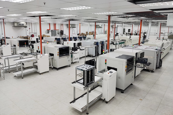
Most plant expansion decisions are framed as equipment questions and then answered as building questions. A PCBA factory process route selection is the second kind: it decides how many times a board leaves the conveyor, what happens while it is off the conveyor, and therefore what the building has to supply in exhaust, floor area, fixtures and people. A factory that buys the machines first and discovers the route second usually ends up with two half-loaded lines, a wave solder machine idling because the through-hole content was overstated, and a coating room that never made it into the budget.
The three routes below are not quality tiers. Each one is correct for a particular product structure, and each one is expensive in a different way. The decision can be made from five inputs: board and assembly structure, through-hole content, the reliability and environment the product is sold into, whether conformal coating is genuinely required, and how the product family is expected to grow. This guide works through each input with a method you can apply to a BOM this week, and treats the line hardware as a consequence rather than a starting point. The hardware side — how many placement platforms, which configuration, how the stations balance — is a separate question covered under the production line configurations this route decision sits on top of; here the line is a fixed block and the question is what gets attached to it.
Strip the trade names away and the three routes differ in one measurable property: how many times a panel leaves the conveyor between the first bare board and the last good board. On an SMT-only route the answer is zero. The panel enters at the loader and travels through printer, SPI, mounter, reflow and AOI without being picked up by hand. On SMT + THT the answer is one or two, because through-hole parts have to be inserted, and insertion is not a conveyor operation. On SMT + Coating the answer is one, at the point where the board has to be masked and sprayed. That single number sets almost everything else: where the work-in-process piles up, which station owns the takt time, how much floor the route needs, and which utility the building must supply. It also explains why two factories with identical placement equipment can have completely different throughput and headcount.
Count the off-conveyor events for a typical double-sided board. SMT-only: the panel is loaded, printed, inspected, placed, reflowed and inspected with no manual handling. Zero events. SMT + THT: after SMT inspection the panel is unloaded into a magazine or tray, inserted at one or more manual or automatic stations, fluxed and soldered at a wave or selective machine, inspected again, sometimes washed, then returned to a belt for assembly and test. One to two events, and each event carries a queue in front of it. SMT + Coating: the panel is unloaded after SMT, masked, coated, cured and inspected, usually as a separate batch rather than a flow. One event, but the following process is no longer paced by the line at all.
The number matters because a conveyor imposes a takt time and an off-conveyor station does not. Once a board is in a magazine, its throughput is governed by people, fixtures and ovens, not by the placement rate of the machine behind it. A PCBA factory process route selection is therefore a decision about where you want the constraint to sit. If the constraint sits on a placement platform, capacity scales with capital equipment. If it sits on an insertion bench or a masking table, capacity scales with labour, and labour does not double when demand doubles unless you plan for it. That is the real trade the three routes offer, and it is worth stating in exactly those terms before any quotation is requested. It also explains why a semi-automatic SMT section can be a rational first step for a product that will later move to full automation: a fast-changeover semi-automatic SMD line keeps the constraint on people while the product mix is still unsettled, which is cheaper than buying automation for a mix you have not measured yet.
The inputs are usually listed as a flat set, which is why the decision stalls. Applied in sequence, each one removes whole options and the remaining choice becomes small. Start with assembly structure. A board thicker than about 2.0 mm, a panel heavier than the conveyor is specified for, or a component taller than the reflow tunnel can pass will force the board off the track regardless of what the BOM says. That single check eliminates SMT-only for a large share of power and industrial products. Second, through-hole content by insertion labour, covered in the next section. Third, the environment the product is sold into, which decides whether coating is a requirement or a preference. Fourth, whether the customer specification actually names a coating standard, because a named standard converts a preference into a non-negotiable step. Fifth, growth: how many product families will share the route within three years, and how often they change over. Only after those five does equipment count, and by then the count is a line-balancing exercise rather than a strategic guess.
The common failure is not choosing THT; it is choosing THT at the wrong scale. A wave solder machine is a large thermal mass. It takes time to reach profile, it consumes energy while it holds, and its fluxer, preheat and nozzle set are all sized for a working range. Run it two hours a day and the machine is economically idle even while it is technically working, because the fixed cost of keeping it ready is spread over very few boards. The same logic applies to a coating line with a curing oven: the oven is the pacing element, and a line that runs one short batch a day pays for a full oven cycle each time. Two practical tests decide this. First, compute the daily loaded hours of the off-conveyor section, not its theoretical capacity — if the section is loaded under roughly half a shift on a normal day, the route is probably too heavy for the volume. Second, check whether selective soldering can absorb the work at that volume: it is slower per joint but starts and stops cheaply, which suits low and mixed volume far better than a wave pot held at temperature.
Being clear about the boundary prevents the discussion from reopening every time someone changes a machine. The route does not decide how many placement platforms you need, which head configuration they carry, or how the line balances — those are downstream questions answered from panel size, placement count and takt time. It does not decide your test strategy either, though it constrains where test sits: on an SMT + THT route, in-circuit test has to come after soldering, because through-hole joints do not exist until the board has been through the wave or the selective nozzle. It does not decide the automation level of the SMT section, which can be semi-automatic or fully automatic on any of the three routes. What it does decide is the building: exhaust capacity, floor area, fire and chemical handling for coating material, fixture storage, and the number of people who have to be present for the line to run at all. Those are the items that are expensive to add later, and they are the reason the route deserves a decision before the machine list.
Through-hole content is normally quoted as a percentage of components, which is the least useful form of the number. A board with 400 parts of which 40 are through-hole reads as ten percent, and that ten percent can be two minutes of work or twelve depending on which parts they are. The ratio that actually predicts cost is insertion labour per panel: how many seconds of hand or machine time the through-hole content consumes, and how many of those seconds sit on the critical path. This section converts a BOM into that number, then maps it onto the three soldering options. The conversion takes about an hour per product family and it is the single most reliable input in the whole route decision, because it comes from your own data rather than from a supplier's claim.
Build the number in four columns. Column one: part count by package family — connectors, terminal blocks, relays, transformers, electrolytic capacitors, axial and radial resistors, headers, mounting hardware. Column two: insertion time per part, measured or estimated in seconds, including picking the part, forming the lead if needed, inserting it, and clinching or taping it. Column three: whether the part can be machine-inserted at all, since odd-form parts cannot. Column four: whether the part is on the critical path, meaning the board cannot move until it is placed. Multiply and sum, and you have insertion seconds per panel. A connector-heavy industrial board can reach several minutes per panel with only thirty or forty parts, while a board with two hundred radial resistors may reach the same total from a completely different direction. That difference matters, because connectors are usually odd-form and hand-placed, while radial parts are the classic case for automatic insertion. Same labour total, different machine decision, and that distinction is exactly what a PCBA factory process route selection has to rest on.
Once you have insertion seconds per panel, the choice becomes coarse and reliable. The table below is a planning guide, not a rule: the boundaries shift with board size, panel count and how tolerant you are of rework, but the shape holds across most electronics assembly. Read it together with the daily panel volume, because the band tells you which tool is right for the work and the volume tells you whether the tool is worth owning.
Insertion labour per panel | Soldering answer | What it implies for the building |
|---|---|---|
Under about 60 seconds, few parts, low volume | Hand soldering at a bench with fume extraction | No THT section as such; a bench, an extractor and a trained operator. Route stays effectively SMT-only with a bench operation attached. |
Roughly 60 to 240 seconds, mixed or odd-form parts | Selective soldering, with hand touch-up for odd-form | One selective machine plus a bench. Small footprint, low standby cost, suits high-mix low-volume and frequent changeover. |
Above roughly 240 seconds, or high panel volume with repeat parts | Wave soldering, usually with automatic insertion upstream | Full THT section: inserter, fluxer, preheat, wave, post-solder inspection, sometimes X-ray and wash. Needs exhaust, floor and fixtures. |
The reason through-hole content persists in modern products is worth understanding, because it predicts whether the content will shrink. Four sources dominate. Connectors and terminal blocks are through-hole because the mechanical load of a cable has to be carried by the board, and a surface-mount pad cannot take that peel force. Power components — transformers, large electrolytics, bridge rectifiers, relays — are through-hole because the thermal mass and the lead geometry need a barrel joint. Legacy or customer-frozen designs keep through-hole parts because requalifying a board is more expensive than continuing to build it. And low-volume industrial or medical variants keep through-hole because the annual quantity never justifies a re-design. None of these four sources disappears when SMT density rises; if anything, the connector share grows as boards get more integrated, since every added function tends to arrive with another cable. That is why treating THT as a legacy step to be eliminated usually fails, and why the honest question is not whether to have a THT section but how much of one.
Assume a control board with 620 total placements of which 54 are through-hole: 18 terminal blocks at 14 seconds each including screw torque check, 12 relays at 10 seconds, 9 electrolytic capacitors at 8 seconds, 6 headers at 12 seconds, and 9 assorted parts at 20 seconds because they need lead forming. That sums to 252 + 120 + 72 + 72 + 180 = 696 seconds, or 11.6 minutes of insertion labour per panel. This is an assumption set chosen to be representative of an industrial controller, not a measurement from any customer. At 40 panels a day that is 464 minutes, or roughly 7.7 hours of single-operator insertion — more than one shift, which immediately argues for two benches or automatic insertion of the radial parts. At 8 panels a day the same board needs 93 minutes, which points to a bench and a selective machine rather than a wave line. The number is the same board; the route is completely different, and the only thing that changed was daily volume. This is the calculation that should precede the quotation discussion.

Adding through-hole capability is rarely one machine. It is a section with its own flow, its own exhaust, its own fixtures and its own inspection logic, and the cost sits as much in the room as in the equipment. The published layout for a full DIP line lists seven elements: the SMT line feeding it, an automatic insertion machine, a wave soldering machine, a selective soldering machine, post-wave inline AOI, X-ray, and a belt assembly line for the manual stations. Not every product needs all seven, and knowing which three can be postponed is where most of the savings are. A factory that buys the full set on day one usually has an X-ray machine and an automatic inserter sitting at low utilization for the first year, while a factory that buys only a soldering machine and no post-solder inspection discovers defects at final test, where they are ten times more expensive to find. This section walks the seven elements in the order that cost arrives, and separates the ones that must exist from the ones that can wait for volume.
The seven elements of a complete DIP line, as published for turnkey builds, are: the upstream SMT line, an automatic insertion machine, a wave soldering machine, a selective soldering machine, post-wave inline AOI, X-ray inspection, and a belt assembly line. The non-negotiable core is the soldering machine plus a way to inspect what it produced. If your through-hole content is axial and radial parts in volume, the soldering machine is a wave; if it is connectors and odd-form parts, it is a selective machine. Everything else is volume-dependent. Automatic insertion only pays when a part family repeats often enough to justify the tooling, which is typically a question of annual panels rather than any single order. X-ray is only mandatory when there are hidden joints — through-hole pins under a connector body, or a BGA on the same board — and unnecessary for open barrel joints that can be seen. A belt assembly line can start as existing benches. The set that can reasonably wait is therefore inserter, X-ray and belt line, in that order of postponement, provided you have arranged the floor so they can be added later without moving the soldering machine. That last condition is the one people forget: a full DIP line built around wave and selective soldering is laid out as a flow, and inserting a station later into a flow that was not designed for it usually means shutting the line for a week.
Soldering produces two different exhaust problems. The fluxer and preheat zone release solvent and flux volatiles, and the wave itself releases solder fume and dross particulate. Both need capture at the source, and the published layout requirement for a semi-automatic line is an exhaust duct with a minimum flow of 500 cubic feet per minute, roughly 14.15 cubic meters per minute, per connection point. That figure is a floor, not a target: it assumes a short duct run and a machine in reasonable condition. Long horizontal runs, elbows and shared headers all reduce the effective capture, so the duct design has to be checked against the machine's own extraction ports rather than against a generic number. The second decision is flux chemistry. A no-clean process avoids a washing step but leaves residue that can interfere with later coating adhesion, which matters if the same board goes on to a coating route. A water-soluble process requires washing, and washing requires a machine, a water supply, a drain and a waste stream. Neither choice is wrong, but the choice has to be made before the machine is ordered, because it determines whether a washer appears on the floor plan and in the utility list.
Wave soldering a board with surface-mount parts on the underside requires a carrier: a machined or routed pallet that masks the SMT area, holds the board flat, and presents the through-hole pins to the wave. Selective soldering needs a fixture too, smaller but still product-specific. Both are per product family, and both consume storage. A factory with thirty active product families and no carrier standard ends up with thirty pallets, each of which has to be found, checked, cleaned and stored between runs — a cost that never appears in an equipment quotation and shows up instead as changeover time and as a shelf wall. Two design rules reduce it. First, standardize carrier outer dimensions and locating features so the conveyor and the machine only ever see one footprint, and let the internal cut-out vary. Second, design carriers for two or three products where the panel outline allows it, and record which products share which carrier in the same place you record programs. The storage itself is real: plan shelving near the line, not in a distant store, because a carrier that takes four minutes to retrieve adds four minutes to every changeover.
The comparison between routes is often made on first-pass cost and settled on rework. Removing a through-hole component is materially harder than removing a surface-mount one: the solder has to be taken out of the barrel before the lead will move, which means a desoldering tool or hot air plus a wick, then the hole has to be cleared, then the new part inserted and re-soldered, and the joint re-inspected. A mis-inserted polarized capacitor found after the wave costs several times what the same error costs at a placement station before reflow, because at the placement station the part is simply lifted off wet paste. This is why post-solder inspection is not optional even when the soldering machine is reliable — it is not there to catch the machine, it is there to catch insertion. The practical guard is a first-article check at the start of every run plus a defined inspection frequency through the run, with the results recorded against the product rather than the operator. Factories that track insertion defects per thousand joints tend to find the same three failure modes repeatedly: wrong orientation, insufficient insertion depth, and a lead that was clinched but not trimmed.
Conformal coating is the most frequently over-applied step in PCBA manufacturing, and the second most frequently under-applied. It is over-applied when a product is coated because a similar product was coated, or because a customer once asked, and it is under-applied when a product that genuinely lives in condensing humidity ships bare because nobody wrote the requirement down. The distinction is not aesthetic. Coating changes the route: it adds an off-conveyor step, a masking operation, a cure cycle, an inspection criterion and a set of chemical-handling obligations. It also reduces repairability, because a coated board has to be stripped locally before any rework. Those are real costs, and they are justified only by a real environment. The method below works backwards from the failure the coating is meant to prevent, which is the only way to decide whether the failure is plausible for your product.
Four conditions justify coating on their own. Condensation is the first: any product that moves between a cold and a warm environment, or is stored in an unheated space, will see water form on its surface, and water plus bias voltage plus ionic residue is the classic electrochemical migration path. Outdoor and marine enclosures, cold-chain equipment and anything shipped by sea in a container fall here. The second is conductive contamination: carbon dust, metal dust, salt fog, or the fine conductive debris of a machining environment. The third is a customer or regulatory specification that names a coating, in which case the argument is over and the only question is which material and thickness. The fourth is a design that cannot meet its clearance and creepage requirements in the space available, where coating is used to protect a gap that is smaller than the bare-board rule would require — a situation where the relevant design standard, such as IPC-2221, allows a reduced spacing only if the surface is protected. In that last case the coating is structural, not cosmetic, and the thickness and coverage have to be specified rather than assumed.
Three conditions argue the other way, and each is often ignored. Repairability is the first: a product with a field-replacement module, a socketed part, or a known wear item will need local stripping, and the repair is slower and less reliable on a coated board than on a bare one. Thermal management is the second: a coating over a component that dissipates heat adds a resistance layer, and on a tightly designed power board that can matter more than the protection gained. The third is the connector and interface population — coating must not enter a connector cavity or a mating surface, which means masking, and the more connectors a board has, the more of the total coating cost is masking labour rather than material. A useful counter-test is to ask what failure the coating prevents, then ask whether that failure has ever occurred in the product's actual field population. If the answer is a hypothetical rather than an observed return, the coating is a preference and should be priced as one. If it is an observed failure mode, it is a requirement and should be specified with a standard and an inspection method.
Brush application is manual: an operator coats defined areas by hand, which suits small volume, partial coverage and prototypes, and costs almost nothing in equipment but a great deal in consistency. Spray application covers a whole board, usually in a booth, with masking applied first; it is fast per board and the standard choice for high volume with simple masking. Selective coating uses a programmable head to dispense or spray only where the program says, which reduces masking dramatically and is the method that makes mixed-volume coating economically viable. The choice changes the labour structure more than the material cost. Brush and spray put the cost in masking and handling, which scales with connector count and board complexity. Selective coating puts the cost in programming and in the fixture, which scales with product count. For a factory running twenty products at low volume, selective coating usually wins on masking alone; for a factory running two products at high volume with minimal keep-out areas, spray with a well-designed mask is faster.

Once coating is decided, the route question shifts from equipment to accommodation. Coating material is a solvent-borne or solvent-free polymer applied in a thin film, and both the application and the cure release volatiles that you do not want drifting across a placement line, where they deposit on optics, on paste and on feeders. That is why a coating step almost never shares an open floor with SMT even when the machines would physically fit. The second reason is cure: a coated board is not finished when it leaves the applicator, it is finished when it is cured, and the cure is a time-and-temperature process rather than a conveyor operation in the usual sense. The third is masking, which is pure labour and is the number that decides whether coating is viable at your volume. Taken together, these three set the room, the oven and the headcount, and they are the reason a coating route is often quoted at a surprisingly similar price to a THT section despite having less machinery in it.
Three things go wrong when a coating step is placed in an open production hall. Overspray travels: a spray booth that is not enclosed and exhausted will deposit a fine film on any surface within a few meters, and that film is difficult to remove from optics and can contaminate paste. Solvent vapour accumulates: the flash-off from a solvent-borne coating has to be exhausted at the source, and a general hall extraction is neither sized nor positioned for it. And dust arrives: a coated board that cures in a dusty space traps particles in the film, which is a cosmetic defect at best and a coverage defect at worst. The practical answer is a bay — an enclosed room with its own exhaust, its own lighting and, ideally, its own access so that boards enter and leave without crossing the placement floor. The bay does not need to be large, but it does need negative pressure relative to the hall so that air moves into the bay rather than out of it. Chemical storage for the coating material itself has to be inside or adjacent, with the local fire and handling requirements applied, because these are flammable liquids in most formulations and the storage rules are not optional.
Curing splits into two families with completely different planning consequences. UV cure is fast, measured in seconds to a minute under the lamp, which makes it attractive for volume — but UV only cures what the light reaches, and the shadow under a tall component stays wet. That means a UV line usually needs a second, slower cure for shadow areas, or a dual-cure material. Thermal cure is uniform but slow, typically tens of minutes in an oven, and the oven becomes the pacing element: the line can apply coating faster than the oven can finish it. Plan the oven from the batch, not from the machine. Assume, for illustration, a thermal cure of 45 minutes at temperature and an oven that holds 60 panels across its belt. The oven then delivers 60 panels per 45 minutes, or roughly 1.3 panels per minute, whatever the applicator can do. If your daily requirement is 200 panels, the oven needs about 2.5 hours of loaded running, which is comfortable. If it is 600 panels, the same oven needs 7.5 hours and becomes the constraint on the whole route. These figures are assumptions chosen to show the arithmetic; substitute your own cure time and oven capacity.
Masking is where coating costs hide. Every connector cavity, every test point that must stay probeable, every mating surface, every optical sensor and every threaded insert has to be protected before the coating goes on and uncovered afterwards. Count them per board and time them honestly. Assume eight keep-out features per board at 20 seconds each to mask, which is 2.7 minutes, plus 1.5 minutes to de-mask and inspect the edges. That is 4.2 minutes of direct labour per board before any coating is applied. At 200 boards a day it is 840 minutes, or 14 hours — two operators doing nothing but masking. This is the calculation that makes selective coating pay: a programmable head that avoids the keep-out areas by program rather than by tape removes most of those 4.2 minutes, at the cost of programming time and a fixture per product. Run the same arithmetic before choosing brush application for a volume product: brushing is cheap to set up and expensive per board, and the crossover arrives sooner than most people expect.
Coating inspection has to be defined before the first production board, because "coated" is not a specification. Three properties matter: coverage, meaning that the intended area is fully filmed with no voids, bubbles or dewetted patches; thickness, which has a target range tied to the material datasheet and to the protection being claimed; and freedom from contamination under the film, since coating over flux residue or dust seals the problem in rather than solving it. The bare board acceptance criteria come from a different document than the coating criteria — a board can pass its own acceptance requirements, such as those in IPC-6012, and still be a poor candidate for coating if residue was left on the surface. Practical inspection combines a visual check under UV light where the material contains a fluorescent tracer, a thickness measurement on a coupon or on a scrap board from the same run, and a periodic adhesion check. Whatever method you choose, put the acceptance criteria in the work instruction with a number and a sampling frequency, because a coating step judged by eye will drift toward whatever the operator last saw as normal.
The three routes differ least in machine cost and most in what the building has to provide permanently. Utilities, floor and people are fixed commitments: they do not scale down when orders do, and they are the items that are genuinely difficult to retrofit because adding exhaust capacity or a coating bay to a live building means construction work around production. The published layout requirements for a semi-automatic SMT line give a useful floor for the SMT portion, and every route addition sits on top of it. Reading those numbers correctly matters: they are minimums for the line as specified, not design targets for a building that will later carry a THT section and a coating bay, and a PCBA factory process route selection that treats a minimum as a target will under-build the building in exactly the places that are hardest to extend. The tables below put the three routes side by side on the same five utilities, then on floor and headcount, so that the incremental cost of each addition is visible rather than buried in a turnkey price.
The published layout requirements for a semi-automatic SMT line cover five utilities. Compressed air: factory air or a separate oil-free compressor, at a pressure above 7 kg/cm². Electrical: single-phase 220 V at plus or minus 10 percent and three-phase 380 V at plus or minus 10 percent, both at 50 or 60 Hz. Exhaust: a duct flow of at least 500 cubic feet per minute, about 14.15 cubic meters per minute. Lighting: 800 to 1200 lux in the working area, with 300 lux as the absolute minimum. Environment: 23 degrees Celsius plus or minus 3, with a general range of 17 to 28 degrees and 45 to 70 percent relative humidity. Those are the SMT line's needs. A THT section adds a second exhaust connection at the soldering machine and, if a wash step is used, water, drain and waste. A coating bay adds its own exhaust, negative pressure, chemical storage and usually a fire-rated enclosure. Each addition therefore raises the utility bill in a way that is visible only if you list the utilities per route rather than per machine.
Utility | SMT only | SMT + THT | SMT + Coating |
|---|---|---|---|
Compressed air | Above 7 kg/cm² at the line | Same, plus air at insertion and soldering stations | Same as SMT only |
Electrical | 220 V single-phase and 380 V three-phase, plus or minus 10 percent | Additional three-phase feed for wave or selective machine and preheat | Additional feed for applicator, cure oven or UV lamps and exhaust fan |
Exhaust | At least 500 CFM (14.15 m³/min) per connection at reflow | Second connection at fluxer and wave; long runs reduce capture | Dedicated bay exhaust with negative pressure relative to hall |
Lighting and environment | 800 to 1200 lux working, 300 lux minimum; 23 ± 3 °C; 45 to 70 percent RH | Same, with higher local lighting at insertion and inspection | Same, plus controlled airflow and no cross-draught over the wet film |
Water, drain, chemicals | Not required | Required only if a water-soluble flux and wash step are chosen | Solvent storage, spill containment and fire-rated storage required |
Floor is where the routes diverge most obviously, and where the estimate is easiest to get wrong because it is usually quoted as machine footprint. Plan the occupied area instead: the machine footprint plus the operator zone, the material zone in front of each manual station, the work-in-process buffer where boards wait between sections, and the fixtures and carriers that belong to the route. Using the same illustrative assumptions throughout, an SMT-only route occupying roughly 12 metres of line length typically needs 25 to 30 square metres of occupied area once the operator side and material staging are counted. A THT section adds insertion benches, a soldering machine, post-solder inspection and a buffer of magazines, which in a mixed layout commonly doubles the occupied area per line. A coating bay is smaller in machine terms but has to be enclosed, so the bay itself plus its access and storage typically adds a room of its own rather than metres of line. These are planning figures, not standards; measure your own layout the same way — footprint plus zones plus buffer — so that the comparison between routes is at least internally consistent.
Route | Added sections | Occupied area, illustrative | Direct operators per shift |
|---|---|---|---|
SMT only | One SMT line, loader to AOI | 25 to 30 m² per line including operator side and staging | 1 to 2, depending on loading and inspection |
SMT + THT | SMT line, insertion benches, soldering machine, post-solder inspection, magazine buffer | Roughly double the SMT-only figure in a mixed layout | 3 to 5, because insertion does not automate itself |
SMT + Coating | SMT line, enclosed coating bay, cure section, masking area, chemical storage | SMT figure plus an enclosed bay, typically a separate room | SMT figure plus 1 to 2 for masking and coating |
Machine quotations do not include people, and route comparisons usually forget them. The right way to count is by function rather than by machine: how many operators are needed for the line to run at its rated output for a full shift, and how many indirect people are needed for it to keep running over a month. Direct operators follow the off-conveyor steps almost exactly. On an SMT-only route the operator loads material, verifies the first article and handles inspection output, and one person can often cover a line while it runs. Add a THT section and the count rises by the insertion stations plus the soldering station plus the post-solder inspector, and those positions cannot be covered by the same person as the SMT line because they are not in the same place at the same time. Add coating and the masking labour described earlier appears, which is directly proportional to keep-out count and volume. The indirect side moves too: a THT section needs a wave or selective process engineer and a fixture owner, and a coating bay needs someone accountable for material shelf life, viscosity and cure verification. Those roles are usually part-time in a small plant, but they have to exist, and a route that adds a process without naming an owner will drift within a quarter.
The route decision is rarely made once and executed in full. Most factories build toward a route over two or three budget cycles, and the sequence they choose determines whether each step is additive or destructive. A good sequence starts with the section that has the shortest setup time and the widest applicability, then adds the sections that require construction, and the discipline it demands is the same one a PCBA factory process route selection demands at the outset: decide the order before the money is committed, not after the first section is running. Following that rule, SMT comes first because it is a conveyor section with no chemistry and no wet process, and it serves every product that will ever pass through the building. THT comes second because it needs exhaust and fixtures but no enclosure. Coating comes last because it needs a room, a chemical store and a cure step that changes the building rather than just the floor. The sequence also has a financial logic: each earlier step generates the volume evidence that justifies the next one, so the decision to add a THT section can be made from measured insertion hours rather than from a forecast.
Three practical rules support that order. First, never install a downstream section before the upstream section can feed it. A THT section installed ahead of a stable SMT output will run in bursts, which is the worst possible load profile for a wave machine and for the people staffing it. Second, leave the physical space for the next section in the original layout, even if the budget does not include it: reserve the floor, run the exhaust header to a capped branch, and size the electrical distribution board for the additional feed. Doing this at the first build costs very little; doing it later means working in a live building. Third, define the trigger for each step before you start, in numbers. The trigger for adding THT might be sustained insertion labour above a set number of hours per week for two consecutive quarters, or a customer requirement that through-hole joints be machine-soldered rather than hand-soldered. The trigger for coating might be a specific product entering the portfolio with a condensation or salt-fog requirement. A trigger written as a number is a decision; a trigger written as an intention is a recurring argument.
Put these eight questions on one page and answer them from documents rather than from memory. One: what is the thickest board and the tallest component in the portfolio, and can both pass the conveyor and the reflow tunnel? Two: what is insertion labour per panel for the top three products by volume, in seconds, measured or estimated with the method above? Three: what is the daily panel volume for each of those products on a normal week? Four: does any product's specification name a coating standard, and if so which one? Five: does any product operate in condensing humidity, salt fog or conductive dust? Six: how many product families will share the route in three years, and what is the average changeover frequency today? Seven: what utilities exist at the intended location, measured rather than assumed — air pressure at the point of use, available three-phase capacity, exhaust duct size and route, floor loading? Eight: who will own the new process, by name and by role? If any of the eight cannot be answered from a document, that gap is the actual next task, and it is cheaper to close it than to choose a route on assumption. Factories that fill this page honestly usually find the route decision has already been made by the answers.
A semi-automatic SMT section is a legitimate first step on any of the three routes, and it is often the correct one when the product mix is still moving. It keeps the constraint on people while volumes are uncertain, which means the capital exposure stays low and the process knowledge stays in the factory rather than in a machine specification. The published layout requirements are the same as for a full line, so the building work done for a semi-automatic installation is not wasted when the line is later automated. What changes is the loading and unloading, the inline inspection and the material handling. Two triggers justify the move to full automation: sustained volume above what manual loading can feed without overtime, and a quality requirement that depends on inline inspection data you cannot collect from a bench. A semi-automatic SMT line sized as a volume entry point is therefore not a compromise on the route; it is the route at its first stage, with the same utilities, the same floor reservation and the same process flow that the later stages will use.
Decide the route from your BOM, not from a quotation
If you are weighing these three routes now, the most useful next step is not a price list. It is a PCBA factory process route selection worksheet built from your own numbers: insertion labour per panel for your top three products, daily panel volume, the environment each product is sold into, and the utilities actually available at the intended location. Send those four items and we will lay the three routes side by side against them — what each route adds in sections, exhaust, floor and people, which of the seven DIP elements you can postpone, and where the coating step becomes the pacing element rather than the last addition. If the through-hole content is the open question, include a BOM extract with part families and quantities and we will convert it to insertion seconds with you, so the wave-versus-selective decision is made on labour rather than on habit. If coating is the open question, list the product's operating environment and any standard named in the customer specification, and we will say plainly whether the coating is a requirement or a preference at your volume. What we will not do is recommend a route from a machine list, because the machine list is the last thing the route decides and the first thing most projects buy.
Yes, and many do, but not simultaneously without planning. The SMT section is common to all three routes, so the same line can feed a THT section on one product and a coating bay on another, provided the changeover between them is designed rather than improvised. The two things that break a shared arrangement are buffer space and people. Boards waiting to enter the THT section and boards waiting for coating both need somewhere to sit in a magazine, and if that space is not allocated, the SMT line stops while the downstream section catches up. The practical solution is a defined buffer position after SMT inspection, sized for one shift of the slower section, plus a rule about which product takes priority. People are the second constraint: the operators for insertion and for masking are not interchangeable with the line operator, so a shared arrangement needs a labour plan that reflects the mix rather than a headcount averaged across products.
Decide from insertion labour per panel and part geometry, not from the machine price. Wave soldering is the right answer when the through-hole content is repeatable, the parts are axial or radial, and the daily volume keeps the pot loaded for a substantial part of the shift. Selective soldering is the right answer when the content is connectors and odd-form parts, when the volume is low or highly mixed, or when the board has surface-mount parts close to the through-hole joints that cannot be masked economically. A useful test is to count how many joints are actually soldered per day rather than per board: a low-volume product with many joints and a high-volume product with few can both fall below the threshold where a wave pot is economic. Many factories end up with both, using the wave for the volume family and the selective machine for everything else, which is a legitimate outcome as long as the split is written down and the fixtures are shared where possible.
No. Outdoor location is a reason to evaluate coating, not a requirement in itself. What matters is whether the board will actually see condensation, ionic contamination or a voltage gradient across a surface that water can bridge. An outdoor enclosure that is sealed and breathable, mounted vertically with a drain path, and operated at low voltage may need no coating at all, while an indoor product in a condensing cold store may need it badly. The question to answer is which failure the coating prevents and whether that failure is plausible in service. If the customer specification names a coating standard, that settles it. If it does not, and no field failure has been observed, coating is a preference, and it should be treated as a cost with a benefit rather than as a default step added because the product goes outside.
It adds queue time at every off-conveyor step, and queue time is usually larger than process time. Insertion, soldering, post-solder inspection and any wash step each create a batch boundary, and boards wait at each boundary until the batch is complete. A route that flows continuously from loader to AOI becomes a sequence of batches once a THT section is added, which is why the same product can take two days instead of one even when the total process time is nearly identical. The way to control it is to set a maximum batch size for each boundary and to run the THT section to that batch rather than to the full order. The other lead-time effect is fixture availability: if a carrier is shared between products, the second product waits for the first to finish, which is invisible in the routing until it happens. Recording carrier ownership per product prevents it.
Usually yes, if the original layout reserved the space and the exhaust capacity. Coating is additive rather than disruptive: it does not change the SMT flow, it takes boards after inspection and returns them, so the line itself keeps working during installation. What cannot be added later without cost is the room and the exhaust. Retrofitting a bay into a live hall means construction work next to running equipment, temporary dust control and a shutdown to connect the duct. If there is any realistic chance that coating will be required within a few years, reserve the floor and run the exhaust header with a capped branch during the first build. That decision costs almost nothing at the time and saves a shutdown later. The equipment itself, applicator and cure, can be selected when the product that needs it is actually in the portfolio.
There is no universal threshold, but the decision is easier when expressed in labour hours per week. Below roughly five hours a week of insertion and touch-up labour, a bench with fume extraction and a trained operator usually beats any machine, because the machine's standby and programming cost cannot be recovered. Between five and twenty hours a week, selective soldering typically becomes attractive because it starts and stops cheaply. Above that, wave soldering and automatic insertion start to pay. The bands shift with part geometry, so the test is always the same: convert the BOM to insertion seconds, multiply by the weekly panel volume, and compare the total against the fixed cost of owning and keeping a soldering machine ready. Factories that run this arithmetic often find that a machine they were about to buy is justified by one product and not by the other nineteen.
Not directly, but it changes the number that matters. The placement count is set by the SMT portion of the board and the takt time the route requires at that station. Adding a THT section does not reduce the SMT work, but it does change when the SMT work has to be finished: if boards queue for insertion, the SMT line can run ahead and buffer, which relaxes its takt requirement. Adding coating has a similar effect on the other end. In practice this means a factory planning a THT section can sometimes run its SMT line at a steadier rate rather than at a peak, which affects utilization but not the machine count. The machine count is decided by placement points, panel size and feeder positions — a separate calculation from the route, and one that should be made after the route is fixed rather than before.