English
 Views: 0 Author: Elsa Long Publish Time: 2026-10-12 Origin: Site


Short answer: the right SMT stencil printer is the one whose working area, automation level, alignment accuracy and inspection interface all match your board size, production volume and product mix. Start with the largest board you actually run and the takt time your line must hit, then choose automation and inspection capability to support those two numbers — not the other way round.
If you need a complete walk-through of the solder paste printer family, see our solder paste printer product hub. This guide goes deeper into the six selection questions buyers ask most often, the trade-offs behind each answer, and the practical way to match printer specification to real production needs.
Table of Contents
Every SMT line is a chain of small mistakes that get amplified down the line. Stencil printing is the first station in that chain, and statistically it is the station where most assembly defects originate. Industry studies and decades of line data agree on the same pattern: a large share of solder defects — opens, bridges, insufficient solder, solder balls — can be traced back to what happened at the printer, not what happened at the placement machine or in the reflow oven.
That single fact shapes how the rest of this guide reads. A printer is not chosen as a standalone piece of equipment; it is chosen as the upstream process owner for everything that follows.
Solder paste printing is a controlled mechanical process: a metal stencil with apertures, a squeegee that pushes paste through those apertures, a board clamped underneath and a vision system that aligns the two. When the parameters stay inside their window — stencil thickness, squeegee pressure and speed, separation speed, alignment offset — the result is a clean, repeatable deposit of solder paste at every pad.
When one parameter drifts outside its window, the line immediately starts producing boards with printing defects. The pick-and-place machine will happily place a BGA on a pad that has no paste under it, and the reflow oven will happily reflow a board that has bridging between two fine-pitch pads. The defect is created at the printer; the symptoms show up three stations later.
The reason printers get this responsibility is simple physics. Reflow soldering is essentially a self-aligning process for many part types: surface tension pulls the component toward the pad and corrects minor placement errors. The same is not true of solder paste printing — once the paste lands on the pad in the wrong shape, reflow will not correct it, the placement machine will not correct it, and AOI downstream will only flag it, not fix it.
For buyers, this means a printer that costs 10–20 % of the total line budget typically has an outsized influence on yield, rework cost and warranty exposure. Choosing it on price alone, without matching it to the actual production conditions, is one of the most common SMT line mistakes.

The first specification to lock down is the largest board or panel the printer must accept. Everything else — frame size, conveyor width, stencil frame, vision travel — is sized around that number.
Most consumer electronics, instrumentation and IoT boards fall inside a 400 × 400 mm working area, which is the de-facto standard for compact and mid-range fully automatic printers. For these boards, almost any printer on the market is technically capable, so the differentiator shifts to other selection criteria below (volume, mix, inspection).
LED panel lighting, industrial controls, home appliances and some automotive electronics routinely use boards longer than 600 mm, often in the 1 200 mm range, and some LED lines go further. A printer with a 400 × 400 mm working area simply cannot clamp these panels, and forcing them onto a small machine with oversize jigs is one of the more expensive mistakes buyers make. The right answer for long boards is a long-board class printer with a working area that comfortably accepts the panel plus a small margin for clamping and fiducial recognition — for example a 1 200 mm or 1 500 mm class machine.
The working area on the spec sheet is not the same as the largest board you can actually run. Real production rarely loads a single bare PCB; it loads either a panelized array or a board mounted on a custom carrier/pallet, and both formats add 20–60 mm of border per side for tooling holes, fiducials and clamping. When buyers compare printers, they should always compare the largest panelized size they intend to run, not the largest bare board.
A useful rule of thumb: take your largest bare PCB, add 40–80 mm to each dimension for panel rails, fiducials and the clamp footprint, and that is the working area you should be looking for. Anything smaller will force a redesign of the panel or a workaround on the line.
Typical application | Bare PCB size (mm) | Recommended printer working area (mm) |
|---|---|---|
Consumer electronics, IoT, instrumentation | ≤ 350 × 350 | 400 × 400 or larger |
Industrial control, telecom base-station modules | ≤ 500 × 400 | 500 × 500 or larger |
LED panel lighting, signage | 600 – 1 200 | 1 200 × 300 class long-board printer |
Home appliance controllers, large-format industrial | 1 200 – 1 500 | 1 500 × 350 class long-board printer |
The second specification to lock down is throughput. Throughput is not just how many boards per hour the vendor quotes in the brochure; it is the cycle time the printer has to deliver in your specific line, against your specific board, with your specific operator.
For new product introduction, prototyping and small-batch engineering, throughput is rarely the binding constraint. What matters is the time it takes to set up a new stencil, calibrate the squeegee pressure, enter the board program and start producing good boards. Manual and semi-automatic printers are often the right answer here, because the engineering team needs direct access to every parameter and the flexibility to iterate on stencil design quickly.
Mid-volume lines — typically a few hundred to a few thousand boards per shift — usually justify a fully automatic printer, because the labour cost of an operator standing at a semi-automatic machine quickly exceeds the depreciation of an automatic one. The breakpoint is rough but consistent in NOP: somewhere between 5 000 and 10 000 placements per shift the labour saving alone pays for the upgrade.
For high-volume consumer electronics, automotive or contract production running multiple shifts, the printer becomes a hard bottleneck. The relevant number is no longer the theoretical CPH (components per hour) but the cycle time per board — how many seconds the printer takes from "board in" to "board out" — and the recovery time after each stencil change. Fully automatic printers in this segment are usually specified with cycle times in the 7–12 second range for a standard board, and they are paired with closed-loop SPI to detect drift before it becomes scrap.
A common miscalculation is to size the printer to match the placement machine's nominal CPH, when in reality the printer is slower than the placement machine. Modern high-speed mounters can place several tens of thousands of components per hour per module; the printer still prints one board at a time. If the placement machine can finish a board in 18 seconds but the printer takes 25 seconds, the printer is the bottleneck and the placement capacity is wasted.
Buyers should always check the cycle time of the printer on the specific board format they intend to run — including panel changeover, stencil wipe, underside support and under-stencil cleaning — not the headline throughput number from a standard test board.
Product mix is the variable that decides whether an inexpensive printer is enough or whether you need a fully automatic one with all the changeover options. It is also the variable that is most often underestimated in the buying decision.
Lines that run essentially one product family for months at a time — typical for power electronics, automotive ECUs or major appliance controllers — can be optimised for that product. The stencil sits in the machine for weeks, the squeegee settings rarely change and the changeover cost is amortised over a very long run. A semi-automatic printer with a fixed conveyor often handles this workload for less capital than a fully automatic machine.
Many EMS companies and contract manufacturers run a family of boards that share a stencil frame size but differ in layout. For these lines the relevant feature is program recall: the printer must store board programs by name, change stencil and squeegee settings without manual recalibration, and confirm alignment from a small set of fiducials rather than teach every board from scratch. This is where the difference between entry-level and mid-range fully automatic printers becomes visible.
High-mix small-batch production — typical of industrial automation, instrumentation, aerospace and defence — pushes the printer toward the upper end of the automation spectrum. The reason is not raw throughput but changeover time. Every minute spent calibrating, loading a new stencil or waiting for the vision system to learn a new board is a minute the line is not producing. For these lines, features like automatic stencil alignment, recipe-driven setup, paste-rolling diagnostics and rail width memory pay back quickly.
Not every "quick changeover" claim on a data sheet is meaningful. The features that actually save measurable time on the line are:
Automatic stencil clamping without manual frame screws, so stencil change is a one-minute job rather than a five-minute one.
Program recall by barcode or job ID, so the operator does not retype coordinates.
Conveyor width memory per program, so the line does not re-measure the board every time.
Vision fiducial library, so common board families reuse the same fiducial strategy.
Auto squeegee pressure calibration, which removes the most common cause of first-board defects after a changeover.
For a structured walk-through of how to choose a solder paste printer specifically for the SMT line you are building, see how to choose a solder paste printing machine for your SMT line.
The choice between manual, semi-automatic and fully automatic is not really a technology question, it is a labour, volume and consistency question. Each class has a clear role, and forcing the wrong class into the wrong production environment is the single most common reason lines underperform.
Manual printers are the simplest configuration: the operator places the board by hand, aligns it to the stencil by eye or with a simple mechanical fixture, and pulls a squeegee across the stencil. They are inexpensive, fast to deploy and forgiving of imperfect fixturing, which makes them a sensible choice for very low-volume prototyping, lab work, repair stations and training. They are not a sensible choice for any line that runs production more than a few hours per day, because the consistency of the print depends entirely on the operator.
Semi-automatic printers add a vision system and motorised axes for alignment and squeegee motion. The operator still loads boards and changes stencils, but the printer handles the precise parts of the process: fiducial recognition, alignment offset calculation, squeegee stroke control. For low-to-mid volume lines where capital is constrained but consistency matters, a good semi-automatic printer is often the best value choice.
Fully automatic printers remove the operator from the print cycle entirely: board in, board out, with stencil wipe, under-stencil cleaning and 2D inspection of the deposited paste as standard options. They are the right answer for any line that runs more than one shift, has a defined takt time, or carries work that is expensive to rework. They are also the only class that interfaces cleanly with closed-loop SPI feedback, which is where modern lines get their biggest yield gains.
The automation choice should be matched to the operating context, not to the technology on offer. Two useful framings:
One operator per shift, low volume: a semi-automatic machine lets the same operator load the printer, run the line and still inspect output without leaving the station.
Three shifts, defined takt, audit-grade output: a fully automatic printer with closed-loop SPI is the only configuration that holds consistency across shifts and operators.
If you are weighing these three classes for a new line and want a side-by-side breakdown of capital cost, cycle time, operator skill requirement and typical use cases, see manual vs semi-auto vs automatic SMT printer — how to decide.

Alignment accuracy is the printer specification that gets the most marketing attention and the least buyer attention, even though it is the one that determines whether fine-pitch and QFN parts can be placed at all. Understanding what the numbers actually mean saves a lot of mis-specification.
Manual and very early semi-automatic printers relied on mechanical pins and operator eyesight. The result depended on the operator and the stencil frame; two operators on the same line would routinely produce two different alignment results. Modern printers use camera-based fiducial recognition: the vision system identifies two or more fiducials on the board, the software calculates the offset and rotation between the board and the stencil, and the stage moves the board into alignment before printing.
For boards with mixed component density or significant thermal mass, a two-fiducial strategy is often insufficient. The board warps slightly between fiducials, and the printer ends up aligning the centre of the board at the expense of the corners. A multi-fiducial strategy — three or more fiducials spread across the panel — gives the software enough data to model and compensate for local warp, and is the standard approach for any board with components at 0.4 mm pitch or finer.
Printer data sheets list two numbers that sound similar and mean very different things. Accuracy is how close the printer can get to a target position in one attempt. Repeatability is how close successive attempts are to each other. For high-volume production, repeatability is the more important number, since the printer is performing the same alignment tens of thousands of times. For NPI and small-batch work where the board changes constantly, accuracy and the vision system's tolerance to imperfect fiducials matter more.
Buyers should ask vendors for repeatability numbers on a fine-pitch QFN or 0.4 mm BGA board, not just the headline 6-axis stage accuracy. The difference between ±12.5 µm and ±25 µm at 4 σ is the difference between printing QFNs at 0.4 mm pitch reliably and not printing them at all.
Component class | Typical minimum pitch | Required printer repeatability (typical) |
|---|---|---|
Passives (0402, 0201) | — | ± 50 µm |
SOIC / QFP | 0.5 – 0.65 mm | ± 25 µm |
QFN / small BGA | 0.4 – 0.5 mm | ± 20 µm |
Fine-pitch BGA / CSP / wafer-level | 0.3 – 0.4 mm | ± 12.5 – 15 µm |
Printing inspection is where the largest yield gains of the last decade have come from. A printer with no inspection is a printer you trust blindly; a printer paired with solder paste inspection (SPI) is a printer you control.
The argument for inline SPI is not that it catches defects — AOI downstream catches them too — but that it catches them at the station where they are created and still correctable. A bridge detected at the printer can be wiped and reprinted on the same board; a bridge detected after reflow requires rework or scrap. The cost difference is roughly an order of magnitude, which is why serious lines consider SPI part of the printing process, not an optional add-on.
Most SPI systems deliver far more data than most lines actually use. The data that matters for printer selection is the same data the operator needs to keep the process inside its window:
Volume per pad, in percent of nominal, with Cpk tracked over time.
Height per pad, with cpk on height being a leading indicator of stencil clogging and paste viscosity drift.
Area/offset/bridging flags, used for go/no-go on the board, not for line performance.
Trend charts by stencil, which tell you when a stencil needs cleaning or replacement before defects appear.
The highest-value SPI integration is closed-loop feedback to the printer: SPI measures the deposit, identifies a drift on a specific aperture, and the printer adjusts squeegee pressure, separation speed or stencil cleaning on the next cycle. Not every printer supports closed-loop feedback to every SPI vendor, so this is a question to settle before the SPI and printer are ordered, not after. For a deeper walk-through of how printer choice and SPI choice together drive first-pass yield, see how matching your SMT printer and SPI improves first-pass yield.
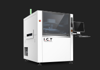
The same logic is what makes the I.C.T 6534 solder paste printing machine for PCB assembly a common recommendation for mid-volume lines that want SPI closed-loop without stepping up to a flagship platform: its vision and stage are designed for the data handoff that an inline SPI system needs.

A good printer with a poorly specified stencil, the wrong squeegee or poorly handled paste will still produce poor boards. These three items belong in the selection conversation even though they are not "printer specifications".
Stencil thickness drives the volume of paste on every pad, and aperture design drives where that volume lands. The standard 0.1 mm stainless-steel stencil is fine for most through-hole-reflow and mixed-component boards; 0.12–0.15 mm is common where a higher volume is required for thermal pads or BGAs; 0.08 mm or finer is used for very fine-pitch work where volume control matters more than volume itself. Foil tension matters because a slack stencil deflects under the squeegee and gives inconsistent transfer, especially on large-area prints.
The squeegee is the variable the operator adjusts most often, and the one most often set incorrectly. A squeegee that is too soft, at too shallow an angle or at too high a pressure will smear paste into apertures; one that is too hard, too steep, or too light will leave the stencil half-filled. The right starting point for a lead-free SAC paste is a 60° metal squeegee at 5–10 kg of pressure and a stroke speed matched to the board area — but the correct values are always confirmed on the first board and held within a small tolerance for the run.
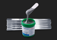
Solder paste is perishable. Storage above 5 °C, exposure to air, repeated temperature cycles and inadequate stirring all change the rheology of the paste before it ever reaches the stencil. A printer is only as consistent as the paste jar it was loaded with, which is why serious lines treat paste storage, lot tracking, jar changeover timing and stencil-top paste recovery as part of the printing process, not as floor hygiene.
A stencil printer is typically expected to run for ten years or more on a production line, which makes the quality of the vendor's after-sales support and documentation more important than the difference between two competitive models on launch day.
Daily, weekly and monthly maintenance should be short, predictable and clearly documented. The items that consume the most line time when poorly designed are squeegee replacement, conveyor belt adjustment, vision window cleaning and stencil frame alignment. Buyers should ask vendors for the documented time per task and confirm that the routine maintenance does not require a service engineer visit.
Spare parts availability is the difference between a one-day repair and a one-week line stop. Buyers should ask for a recommended spare parts list with part numbers, the local stocking policy of the vendor or distributor, and the lead time on the parts that fail most often (squeegee motors, conveyor belts, vacuum generators, vision boards).
A new printer is only as productive as the team that runs it. Vendor training — for operators, process engineers and maintenance technicians — should be on-site, hands-on and structured around the actual boards the line will run, not a generic classroom session. For buyers who want to standardise training across plants or languages, our printable reference set is published as a shared training handbook for SMT stencil printing; ask your account manager for the latest local-language version.
For readers comparing concrete machine specifications, three configurations from the I.C.T range cover the most common selection paths buyers face: a compact automatic printer for general SMT assembly, a 1.2 m class long-board printer, and a 1.5 m class printer for the largest LED and appliance panels.
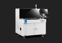
For general SMT lines running boards up to 400 × 400 mm in mid-volume production, the I.C.T 6534 SMT solder paste printing machine for PCB assembly is the standard configuration. It pairs a vision-driven alignment system with a programmable squeegee head, supports inline SPI handoff, and is sized for lines that need automatic operation without stepping up to a flagship platform.
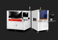
LED panel lighting and signage production typically run boards in the 600–1 200 mm length range, which is beyond the working area of a compact printer. The I.C.T 1200 1.2 meter SMD stencil solder printer machine extends the working area to 1 200 mm while keeping the same vision, squeegee and conveyor architecture as the smaller platform, so an existing operator team does not have to relearn the line.
For home appliance controllers, industrial drivers and the largest LED formats, a 1.5 m class printer is the right answer. The I.C.T 1500 long-board fully automatic LED PCB stencil printer covers panels up to 1 500 mm with the same fully automatic paste handling, vision alignment and SPI integration as the smaller machines, so a plant does not give up consistency as it moves to longer boards.
Configuration | Working area (mm) | Typical application | Reference model |
|---|---|---|---|
Compact automatic | 400 × 400 | General SMT assembly, mid volume | I.C.T 6534 |
1.2 m class long-board | 1 200 | LED panel lighting, signage | I.C.T 1200 |
1.5 m class long-board | 1 500 | Appliance controllers, large LED | I.C.T 1500 |

The questions below are the ones a process engineer should answer before a printer is ordered. They are listed in the order they should be answered, because each later question depends on the earlier one.
What is the largest panel you intend to run, including rails and fiducials? Set the minimum working area; everything else is sized around it.
What is the cycle time the printer must deliver, on that panel, end to end? Cross-check the vendor's published cycle time on a real board, not the headline number.
How many shifts will run, and how many operators will be available per shift? Decide manual / semi-automatic / fully automatic from the answer.
How many product changeovers will the printer perform per shift? Decide whether quick-changeover features are essential or nice-to-have.
What is the finest pitch on any board the line will see in the next three years? Decide the repeatability class, and confirm it on a fine-pitch QFN or BGA, not on a generic stage accuracy number.
Will the line run inline SPI? If yes, decide which SPI vendor, and confirm closed-loop compatibility with the printer before purchase.
What is the planned service and spare parts support model? Confirm local stocking, training and documentation in the language your team works in.
What is the five-year total cost, not just the purchase price? Include energy, consumables, expected maintenance and the labour differential between manual, semi-automatic and fully automatic.
When the same answers are given to multiple vendors, the comparison becomes a specification comparison rather than a brand comparison, and the buying decision becomes much easier to defend internally.
Need help matching a printer to your boards and volume?
Send us your largest panel size, your target cycle time, your shift pattern and the finest pitch on any board you intend to run. Our team will return a short list of printer configurations from the I.C.T range that fit your production needs, with cycle time estimates and the SPI integration options available for each.
It is the working area matched to your largest panel, not the headline accuracy or throughput. A printer that cannot physically accept your panel will not print it no matter how accurate the stage is. Start with the largest panel you intend to run, add margin for rails and fiducials, and use that number as your minimum working area. Everything else — accuracy, throughput, inspection — is decided after the working area is locked in.
AOI can catch printing defects after reflow, but by then the cost of correcting them is roughly an order of magnitude higher than catching them at the printer. For high-volume lines with defined takt time, inline SPI is the standard because it stops the defect at the source and feeds data back into the printer for correction on the next board. For prototyping or very low-volume lines, AOI alone is often sufficient. The decision is essentially a volume and rework-cost calculation, not a technology preference.
Once your panel length exceeds roughly 500 mm, the working area of a compact printer starts forcing design compromises on the panel: shorter panels, panel breaks in the middle of an LED strip, or custom carriers. LED panel lighting, home appliance controllers and large industrial boards routinely run in the 600–1 500 mm range, and these applications need a long-board printer with a working area that accepts the full panel plus margin. Choosing a compact printer for these applications is one of the more expensive line mis-specifications, because the workaround usually has to be undone within a year.
Match the class to your operating context. Manual printers fit prototyping, lab work and very low-volume repair stations. Semi-automatic printers fit low-to-mid volume lines where one operator runs the printer and the rest of the line, and where capital is constrained. Fully automatic printers fit any line that runs more than one shift, has a defined takt time, or carries work that is expensive to rework. The breakpoint is roughly the volume at which the labour saving of removing the operator from the print cycle pays for the additional capital cost of an automatic machine.
For 0.4 mm pitch QFN and small BGA, look for a printer repeatability of ± 20 µm or better. For 0.3 mm pitch wafer-level or very fine-pitch BGA, the requirement tightens to roughly ± 12.5–15 µm. Always confirm these numbers on a fine-pitch test board rather than on the headline six-axis stage accuracy, because the difference between the two is the difference between printing QFNs reliably and not printing them at all.
Physically yes — most fully automatic printers can be slowed down, run with manual loading and used for NPI work — but the operating economics are poor. A printer that spends half its life being used as a semi-automatic machine is wasting its capital cost. Most serious lines run a smaller semi-automatic or manual printer for NPI and engineering work, and reserve the fully automatic machine for the high-volume production line. The two machines together usually cost less than the productivity loss of misusing the flagship machine.
It is one of the most important selection criteria in practice, even though it is rarely the first one buyers ask about. A stencil printer is expected to run for ten years or more, and the difference between a one-day repair and a one-week line stop is entirely a function of the local service network. Before purchase, ask the vendor for a recommended spare parts kit with part numbers, the local stocking policy, and the documented response time for a typical service call. The answers will quickly sort serious vendors from sales offices.