English
Views: 0 Author: Elsa Long Publish Time: 2026-10-30 Origin: Site


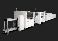
Balance multiple Hanwha mounters by allocating placement work according to measured processing time, component handling requirements, feeder access, and the output interval the rest of the line can sustain. Equal component counts rarely create equal station times. When evaluating a multi-machine SMT placement configuration, start with the actual PCB panel, production mix, and quality requirements, then adjust the placement split until no station repeatedly holds up good output.
Effective Hanwha SMT line balancing for multiple mounters connects six decisions: which machine places each component, where its feeders sit, which station sets the pace, how the PCB is panelized, how often the product changes, and how printing, inspection, and reflow constrain output. A balanced program should work during a representative production run, including replenishment and normal interruptions. This guide explains how to develop that balance and how to check whether another mounter would actually help.
Begin with required good boards per shift and the usable production window. Keep boards, panels, and placement counts separate. A six-up panel produces six boards only when all six are accepted; a machine counter showing panels cannot be compared directly with an order quantity expressed in boards. For a mixed schedule, calculate demand by product family and distinguish production time from planned breaks and scheduled changeovers.
As an illustrative planning example, producing 2,400 good boards in 360 scheduled production minutes requires an average of 6.67 good boards per minute. With six boards per panel and an assumed 100% yield, that corresponds to one panel every 54 seconds. That 54-second figure is a demand-derived ceiling for the average output interval, not a recommended machine setting. Actual process time must allow for the losses and yield observed at the factory. Do not subtract a loss from available time and then apply the same loss percentage again.
The output of a serial line is governed by its slowest effective constraint over the relevant production window. Adding the rated component-per-hour figures of three machines does not reveal the line's panels per hour. The machines process successive panels concurrently, but each panel still has to pass through the required stations. The distinction between a panel's total journey time and the interval between completed panels is central to a useful balance calculation.
Record each mounter's active placement time, board transfer, clamping, fiducial recognition, and normal handling operations. Check which of those activities overlap on the installed machine and conveyor configuration. If a program report already includes recognition or transfer, do not add it twice. Use the same start and stop events when comparing stations, and record blocked and starved time separately from active processing time.
Create a baseline sheet containing panel identity, board dimensions, placements per panel, component families, feeder requirements, nozzle requirements, and measured station intervals. Confirm machine capability before optimizing workload: installed heads, available options, board handling, feeder interfaces, and supported component packages can restrict what can move between stations. Use the application criteria for selecting a Hanwha mounter to structure those checks. A feasible assignment must come before a fast assignment.
A small passive component and a connector each count as one placement, but their processing burdens can differ substantially. Pickup conditions, vision checks, allowable acceleration, placement force, nozzle selection, and travel affect how long a component takes. A station with fewer placements can therefore become the bottleneck if those placements need more handling. Allocate work using a supported program estimate, then verify that estimate on the real product.
Group the BOM into practical processing families: frequently repeated passives, ordinary integrated circuits, packages requiring additional inspection, and components with special pickup or placement conditions. Mark the machines on which each family is actually qualified. Do not assume that every Hanwha machine in a mixed installation can run the same feeder, nozzle, board size, or component without configuration changes. Machine condition and installed accessories matter as much as the model name when evaluating existing or used equipment.
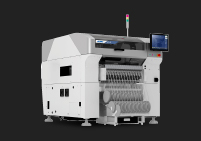
When reviewing a DECAN S1 equipment configuration, request the installed machine's configuration and a trial using the intended panel. The product listing is a starting point for discussion, not proof of the cycle time that your BOM will achieve. Apply the same evidence standard to every proposed station.
Suppose a hypothetical three-mounter program produces station intervals of 42, 61, and 47 seconds under comparable conditions. The second mounter sets a placement-stage ceiling of roughly one panel every 61 seconds. The engineering question is which qualified component group can move from that station to another without creating additional feeder, nozzle, or travel penalties. Moving half its component count is unlikely to be the best first experiment.
An estimated reassignment might produce 49, 52, and 50 seconds. Treat those figures as an optimization proposal until the revised programs run successfully. Confirm that the receiving station has suitable feeders and nozzles, that placement access remains acceptable, and that quality results remain stable. Moving parts also changes head travel and pickup combinations, so the original time attributed to a group will not necessarily transfer unchanged to another machine.
Keep a controlled record of the original and revised assignments. Change one meaningful group at a time, compare the same panel revision, and record both cycle performance and defects. A few seconds saved in placement do not justify a package assignment that produces more pickup errors, rejected parts, or rework. The useful objective is repeatable good-board output with manageable setup effort.

Component allocation and feeder layout must be optimized together. A machine may have enough nominal feeder positions yet lack sufficient usable space once feeder widths, tray units, access requirements, and reserved setup positions are considered. Count occupied space for the actual feeder types and check the installed configuration. A count of unique BOM part numbers alone is an incomplete capacity check.
Place frequently used components where the machine's supported optimization tools and trial results indicate efficient pickup sequences. Avoid a universal rule such as putting every high-use reel at the center: the best arrangement depends on the head structure, feeder banks, PCB placement coordinates, and pickup combinations. A layout that helps one component group can make another group's movements less efficient. Re-run the program estimate after the feeder arrangement changes.
For repeated parts, duplicate feeding positions can sometimes support a more effective assignment across machines or heads. That option consumes feeders, reel inventory, setup effort, and space. Confirm that the installed hardware and programming software support the proposed arrangement and that the gain survives replenishment. The feeder formats available for SMT setup planning should be evaluated against the exact machine interface and tape requirements; a multi-brand listing does not establish interchangeability.
Nozzle availability can limit a workload split even when feeder space is adequate. Several components may share a nominal nozzle category while needing different pickup verification, clearances, or handling settings. Frequent nozzle exchanges can offset the benefit of moving work away from a busy station. Use the practical checks for matching feeders and pickup nozzles to check the component, feeder, and head as a complete pickup system.
Prepare a replenishment plan for the highest-consumption reels. Estimate consumption per panel, observe actual reel-change or splice procedures where supported, and check whether the operator can reach the required feeder safely during the production sequence. A fast nominal cycle with frequent line stops can deliver fewer good panels than a slightly slower setup with reliable replenishment. Record stops by cause rather than hiding them inside an average cycle time.
Before releasing a feeder map, verify part number, feeder position, orientation, tape width, nozzle assignment, and the applicable machine program revision. Use the factory's existing verification method and traceability controls. The final map should be reproducible by the next shift; a balance that depends on undocumented operator adjustments will be difficult to sustain.
A mounter that looks busy is not necessarily the line constraint. Observe several stations over the same time window and classify each interval as processing, blocked by downstream equipment, starved of incoming panels, or stopped for a recorded reason. This reveals whether the mounter's own workload is slow or whether it is reacting to a problem elsewhere. A high utilization percentage without its definition can be misleading.
Queues are useful clues when interpreted with those states. A repeated queue before one station and frequent starvation after it suggest a capacity restriction at that station. However, buffer size, transfer handshakes, batch release, and inspection holds can produce similar visual patterns. Review the sequence of events rather than relying on a single photograph or momentary queue. Use machine timestamps or a coordinated observation sheet where line data are unavailable.
For a prospective DECAN F2 placement station, define its expected role using the intended workload and installed configuration. Ask whether it will absorb a qualified component family, replace an unreliable station, or reduce a demonstrated placement constraint. Buying another machine without identifying the limiting process can simply move the queue.
Consider a deliberately simplified example in which three mounters sustain 49, 52, and 50 seconds per panel, while a downstream inspection station sustains 58 seconds. With no other losses, the 58-second process limits the long-run interval. Reducing the second mounter to 48 seconds will not by itself raise the line above that downstream limit. There may still be useful resilience or staffing benefits, but those need their own justification.
Observed pattern | What to investigate | Practical next action |
|---|---|---|
One mounter processes continuously while the next waits | Placement workload, pickup retries, component handling | Reassign a qualified group and repeat the trial |
Several mounters wait with panels inside | Downstream blocking, conveyor handshake, inspection hold | Trace the first blocked station and its cause |
All mounters repeatedly wait for incoming panels | Printer, SPI, loader, release practice | Measure upstream intervals and stop causes |
Short fast runs alternate with long interruptions | Replenishment, faults, recovery, operator workload | Compare sustained output and loss categories |
Repeat observations after each substantial change because the bottleneck can migrate. Also evaluate different product families: the same installation may be placement-limited on one PCB and inspection-limited on another. Acceptance criteria should therefore include representative products, not only the easiest demonstration board.
Panelization changes the placement count, travel pattern, handling frequency, and number of boards produced by each completed panel. A larger array may spread transfer and recognition overhead across more boards, but it also requires more placements per panel. Compare the resulting output in good boards per hour and include quality and handling constraints. A faster panel interval is not automatically a better board output rate.
For illustration, a four-up panel at a stable 40-second interval produces a theoretical 360 boards per hour: 3,600 divided by 40, multiplied by four. A six-up panel at 54 seconds produces a theoretical 400 boards per hour under the same no-loss, 100%-yield assumptions. If the six-up design causes more rejects, unsupported handling, or an unacceptable soldering result, the theoretical gain is not sufficient grounds to choose it. These numbers demonstrate the comparison method and are not Hanwha performance claims.
Examine rail clearance, fiducial visibility, tooling support, board warp, array orientation, and access to components placed on earlier machines. Confirm whether the complete panel is within every station's supported handling range, including printer, inspection, conveyors, reflow, and depaneling. A panel accepted by the mounter may still be unsuitable for another operation.
Long LED boards illustrate why component repetition alone cannot predict balance. Many repeated LEDs may simplify the BOM but still create long placement travel, support requirements, orientation checks, and downstream handling constraints. Review the panel and component considerations for LED placement when that product family is relevant. Do not generalize an array that works for small rigid PCBs to long or flexible assemblies.
Panel orientation also changes pickup-to-placement travel and may affect how work is distributed among machines. Evaluate alternative orientations only after checking conveyor direction, board support, fiducials, process requirements, and available program options. Compare program estimates and trial results using the same measurement boundaries. Keep the revision of the panel drawing linked to the program revision so later engineering changes do not invalidate the balance record.
Include the consequences of partial panel rejection and rework. The production team needs an agreed method for handling bad circuits within an array and for communicating those conditions to subsequent equipment where supported. Otherwise, nominal board output can conceal scrap or manual work. Select a panel design that supports stable accepted output through the full route, including separation and final inspection.
For a long run, reducing the panel interval can be valuable. For small batches, feeder preparation, program verification, first-article approval, and ramp-up may dominate elapsed time. Evaluate the time required to finish the planned good quantity, including changeover and normal production losses. A setup optimized only for one board can be a poor choice for a schedule with frequent product changes.
A hypothetical 120-panel batch illustrates the trade-off. Setup A takes 45 minutes to change over and then runs at 45 seconds per panel, giving 135 minutes before additional losses: 45 minutes plus 90 minutes of running. Setup B takes 20 minutes to change over and runs at 50 seconds per panel, giving 120 minutes: 20 minutes plus 100 minutes of running. B finishes the small batch earlier despite its slower steady-state interval. At larger quantities, A may become preferable.
In this simplified comparison, A incurs 25 extra setup minutes and saves five seconds per panel. The break-even quantity is 300 panels, calculated as 1,500 setup seconds divided by five seconds saved per panel. Actual scheduling must include the losses, yield, labor constraints, and approval time of both setups. Use this calculation to identify which trial data matter, not to declare a universal batch-size rule.
Group products by meaningful overlap in components, feeder configuration, board handling, and process requirements. Retaining common feeders can reduce setup effort, but it also reserves space that another product may need. Check the worst-case feeder occupancy within the family and whether common positions create excessive travel or nozzle changes. The Hanwha production-family planning approach helps connect equipment allocation to a varied order book.
Separate work that can be completed offline from work that stops the line. Prepare verified feeders, material kits, approved programs, and the required pickup tooling before the outgoing batch ends, where the installed equipment and factory process allow it. When checking Hanwha and Samsung nozzle references, confirm the exact head interface and approved component use. Similar naming in a listing is not evidence that a nozzle fits every machine.
Measure changeover from a defined last-good event to a defined first-good event. Record feeder exchange, width adjustment, program loading, verification, first-article approval, and recovery separately. This allows the team to improve the largest delay without assuming that every minute belongs to the placement program. Keep quality approval in the schedule rather than treating it as invisible time.
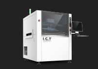
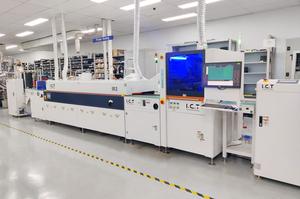
Printing, solder paste inspection, placement, reflow, and inspection must sustain compatible output intervals. Inspect the actual route because not every line uses the same equipment or inspection sequence. Include loader operation, transfer handshakes, buffer behavior, inspection review, and unloading. A short isolated mounter trial does not establish the output of the connected line.
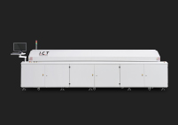
For reflow, the acceptable thermal process sets the permissible conveyor conditions. Where a conveyor carries one panel across its width and panels have a consistent longitudinal pitch, the approximate entry interval is pitch divided by conveyor speed, using consistent units. Pitch includes the panel length in the travel direction and the required gap. Confirm the actual loading arrangement and profile; do not increase speed or reduce gaps solely to make a spreadsheet balance.
Buffers can absorb brief differences between stations, but they cannot eliminate a persistent capacity deficit. Record buffer occupancy during the trial and distinguish intentional process control from uncontrolled accumulation. Increasing work in progress can lengthen lead time and conceal the origin of a stop. Review handling and any applicable process time limits before enlarging a buffer.
Agree the trial product, panel revision, component mix, operator conditions, replenishment method, and observation window before testing. Include representative difficult packages and normal production activities. Record program versions and hardware configuration so the result can be reproduced. Compare sustained output with the demand target, and retain both raw observations and the assumptions used to summarize them.
Acceptance item | Evidence to retain | Decision supported |
|---|---|---|
Station workload | Comparable cycle records and waiting states | Whether placement work is balanced |
Connected-line output | Accepted boards, elapsed time, panel count | Whether the planned demand is achievable |
Material handling | Feeder map, replenishment events, pickup losses | Whether the balance survives routine operation |
Product quality | Inspection results and defect disposition | Whether faster output remains acceptable |
Product change | Last-good to first-good timing by activity | Whether the schedule fits the available shift |
Use the results to decide whether to reassign components, revise feeder positions, change panel design, reduce setup losses, or address another station. Consider additional placement equipment only after the evidence shows a placement capacity or capability gap that the existing configuration cannot reasonably resolve. For a supplier discussion, prepare the BOM, placement data, panel drawing, product mix, required good output, and current station observations. Those inputs support a configuration proposal tied to the factory's actual work.
Should every Hanwha mounter place the same number of components?
No. Equal counts can produce unequal processing times because components need different pickup, vision, travel, and placement operations. One machine may also handle packages that another installed configuration cannot accept. Start with a qualified assignment, compare estimated station times, and validate the split on the real panel. Adjust coherent component groups while checking feeder space and nozzle requirements. The target is a repeatable output interval with acceptable quality, not identical placement totals on every machine. Record the final allocation so it can be reproduced after a product or program revision.
Will adding another mounter always increase SMT line output?
No. Another mounter increases output only when it resolves a relevant placement capacity or capability constraint and the connected equipment can support the resulting flow. If printing, inspection, reflow, or material replenishment already limits output, the additional machine may spend much of its time waiting. Measure station processing, blocked time, starved time, and interruptions over the same production window. Then compare the expected improvement with setup effort, available space, staffing, and maintenance needs. A product-specific connected-line trial provides better purchasing evidence than adding together catalog placement rates.
When should the same component be loaded on more than one machine?
Duplicate loading can help when a frequently used part must be divided between qualified machines to reduce a placement constraint. It can also support certain setup strategies, depending on the installed equipment and software. The trade-off is additional feeders, reel inventory, verification work, and occupied space. Check that duplication actually shortens the sustained output interval after travel, nozzle use, and replenishment are included. For small batches, preparing two positions may cost more time than it saves. Compare the complete batch result before making duplicate loading the standard arrangement.
Can a larger PCB panel make a balanced line slower?
Yes. A larger panel can increase placement travel, handling time, support demands, inspection workload, or downstream pitch. It may also exceed a station's supported dimensions or create process-quality problems. Evaluate good boards per hour rather than panels per hour alone, since a slower panel interval can still produce more boards when the array contains additional circuits. Confirm quality, yield, reflow conditions, and depaneling requirements before choosing the larger array. Keep the approved panel revision linked to the placement programs and repeat the balance check after an engineering change.
How often should a multiple-mounter line be rebalanced?
Recheck the balance when changes affect the workload, capability, or production schedule. Typical triggers include a new BOM revision, different panelization, a changed component package, revised feeder positions, a different product mix, or persistent pickup and replenishment losses. Maintenance or hardware changes can also alter the baseline. Routine output and stop records help identify whether the previous assignment still works. Begin with the changed condition and compare it with the retained baseline; a full program rebuild is unnecessary when a focused correction restores stable good-board output.