English
Views: 0 Author: Vinci Zhang Publish Time: 2026-10-14 Origin: Site


Component shifting during reflow is almost always a placement and print problem that only becomes visible after the solder melts, not a thermal problem the oven profile created. The part sits where the placement machine left it, the paste melts, and then a small net force — usually between the wetting pull of self-alignment and gravity, buoyancy, or the convection airflow — slides or rotates the part off its pad. This article covers what shifting is, the cause families that produce it, how to diagnose it, and how to build a process that keeps parts in place.
For the broader picture, the complete guide to reflow soldering defects explains how to classify any reflow defect before changing settings. Shifting sits in the component-movement family, which the companion article on common reflow soldering defects lists alongside tombstoning, floating, and wicking. The view below is about one defect only.

Shifting is a position error that appears only after reflow, and naming it correctly is the first step toward fixing it. The part ends up off its pad, rotated, or both, and the joint that forms is off-center or incomplete. The defect is easy to see at AOI but it is caused upstream, so the fastest fix is almost never to touch the oven.
Shifting, skew, and rotation are the same event from different angles. A lateral move off the intended position is shifting; the same move expressed as the part turning about its center is skew or rotation, and they usually happen together. The label does not change the cause families, so this article treats them as one behavior: the part moved when it should have stayed.
A shifted part looks placed correctly when it leaves the mounter, sitting in the paste. The move happens during the molten window, when the solder is liquid and the part is free to slide. That is why shifting is a reflow defect in name but a pre-reflow condition revealed by reflow. The key point is that the oven did not create the offset, it exposed it, so looking for the cause after the oven is looking in the wrong place.
Shifting and floating are related but distinct, and confusing them sends you to the wrong fix. A shifted part moves a modest distance and settles, usually still on or near the pad. A floating part lifts off and can travel much farther, sometimes swimming across the deposit. Both involve the same wetting-versus-buoyancy balance, but floating is driven harder by buoyancy and airflow and hits the lightest parts on the most generous deposits. Our article on why components float during reflow covers the float case; for shifting the dominant lever is placement offset and paste volume.
Lighter parts with smaller termination area shift more readily than heavy, well-anchored parts because the net force needed to move them is smaller; small chip capacitors and resistors, especially the smaller metric sizes, are the usual victims. A low component-mass-to-pad-area ratio makes any imbalance easier to move. Large integrated circuits are less likely to shift as a whole, though leads can draw off. The pattern on your line matters most: a shift that follows one component type points to geometry and paste interaction, while one that wanders points to a global issue such as airflow or conveyor vibration.
Every shifted part is the result of a force balance. Self-alignment pulls the part toward pad center; gravity, buoyancy, and the convection airflow inside the oven push or drag it the other way. When the net force is near zero, the part stays. When the balance tips, the part moves. Understanding the individual forces is what lets you predict which change will help.
Self-alignment is the surface-tension effect that pulls a component toward the center of its pad geometry once the solder melts. It is the reason placement machines can run looser tolerances than the pad size might suggest, because small offsets correct themselves during the molten window. It is the main force fighting everything else here. It works best when both terminations wet at the same time and the part sits on both deposits. It is not infinite, and it cannot recover an offset that is too large or a part not in contact with the solder on both sides.
Gravity is a steady downward force that, on a flat board, mostly helps keep a part seated — but it becomes a problem on boards run vertically or at an angle, and it interacts with the molten solder film beneath the part. Buoyancy is the upward push from the molten solder and any vapor beneath the component, and it is the more relevant force for shifting and floating. A part on a thick, fully molten deposit experiences a buoyant lift that reduces the friction holding it down, making it easier for any sideways force to slide it.
The convection airflow that heats the board also exerts a force on loose components, especially light ones. Hot air moving across the chamber can push a part sitting on a low-friction molten solder film, and because the airflow has a direction, the push is not random — parts tend to drift downwind. This is one of the most overlooked causes of shifting, because the airflow is invisible and the oven looks normal. Uniform airflow across the chamber width reduces the directional push, while a strong or uneven jet can systematically move the same corner of every board.
Once the paste melts, the component is effectively resting on a thin liquid film that acts like a low-friction bearing: it lets self-alignment slide the part gently to center, but it also lets any other force slide it away. The lower the friction, the smaller the net sideways force needed to move the part a visible distance. This is why paste volume matters so much — more paste means a thicker, more buoyant film and less grip. Keeping the deposit just sufficient to form the joint is one of the cleanest ways to reduce shifting.
None of the individual forces above causes a shift by itself in most cases; what matters is the net force while the solder is liquid and before it solidifies. The practical implication is that you rarely need to eliminate a single force; you change the balance. Reducing paste volume lowers the buoyant lift, tightening placement shrinks the starting offset, and smoothing airflow removes the directional push.

The most common root cause of shifting is a placement offset already present when the board left the mounter and simply carried into reflow. The oven did not move the part from the pad center; the part was never there to begin with. This is why the first check for any shift is the placement data, not the profile.
A small placement offset is usually harmless because self-alignment pulls the part back as the solder melts. The trouble starts when the offset is too large for the centering force to recover before the solder freezes, or when the part sits on only part of one deposit. At that point the offset leaving the mounter is exactly the offset seen after reflow, frozen into a bad joint. The lesson is direct: the placement accuracy you tolerate is the shift risk you carry, and tightening placement is the cheapest lever against shifting.
The component-mass-to-pad-area ratio is a useful way to think about shift risk. A light part on a small pad area has little mass holding it down and little pad area generating centering force, so a modest imbalance moves it easily. A heavier part or larger pad generates more restoring force and grip, which is why small passives shift more than large packages and why the same paste volume that suits one component can float another. When you introduce a small-case-size part, expect shift risk to rise unless placement and paste are tightened.
Self-alignment has a well-known practical limit, often described as roughly half a pad width of recoverable offset, beyond which the part will not center. That figure is a rule of thumb rather than a guaranteed value, because it depends on pad geometry, deposit volume, and how symmetrically the part wets. A rotated or tilted part may bridge one termination while barely touching the other, which self-alignment cannot untangle, and on a small chip that same imbalance drives tombstoning — the heat-balance version is covered in our article on preventing tombstoning in reflow.
You cannot manage a placement offset you do not measure. The mounter's claimed accuracy is a specification, not a statement about your board on your shift, and it drifts with wear, nozzle condition, and program quality. The useful practice is to pull placement deviation data by component type and trend it, so you can see average offset creep toward the recoverable limit. First-article inspection should include a placement check, not just a solder check, because catching an offset before reflow costs nothing and after costs a rework cycle.

Paste volume is the second member of the shifting cause family, and it works together with placement. Too much paste creates a thick molten film that floats and frees the part to drift; too little leaves the part unsupported or sitting on only one deposit. Both extremes move the part, which is why paste control belongs in any shifting investigation.
Excess paste contributes directly to shifting because it builds a thicker, more buoyant molten film beneath the component. With more solder under it, the part lifts slightly and loses grip, so any sideways force — airflow, a residual placement offset, or an uneven wetting pull — can slide it. This is the same mechanism behind floating, only milder. The fix is a volume reduction at the stencil, not a profile change. This is the same mechanism behind floating, only milder. When shifting appears after a paste or stencil change, volume is the first suspect.
Volume is not the only paste variable; deposit shape matters too. A deposit centered and uniform under both terminations lets self-alignment act symmetrically and pull the part straight to center. A lopsided deposit, or one that bridges toward one side, gives the part an uneven start and a directional wetting pull that can become a shift. Print quality is part of shift control and must be measured, not assumed. SPI data on deposit height and area tell you whether the printer is still producing the geometry the process was built around.
A partial deposit or a skip is the opposite extreme and also produces movement. If one termination sits on a full deposit and the other on little or none, the wetting force is one-sided and the part is pulled or tilted rather than centered. It may also be physically unsupported on one side, so any vibration or airflow tips it. Skips usually trace to a clogged or partially blocked aperture, a stencil not cleaned on schedule, or paste dried in the apertures during a pause. The fix belongs at the printer.
Stencil aperture design sets the deposit volume and shape for every part, so it decides shift risk at the design stage rather than on the line. Aperture area ratio and stencil thickness together set how much paste prints and how cleanly it releases, and both feed the molten-film thickness that governs float and drift. The relevant guidance is captured in standards such as IPC-7525 on stencil design, which frames the aperture rules that keep deposits in the useful band. Symmetric pad and aperture geometry for both terminations keeps the centering force balanced.

Mechanical disturbance is the third cause family. Even a perfectly placed, correctly pasted part can be pushed if the board is shaken, poorly supported, or seated unevenly as it travels through the oven. These are line-mechanics problems, not process-recipe problems.
Conveyor vibration is a real but often ignored source of shifting. A board that rattles on the rails, or passes over a worn or misaligned section, receives small mechanical kicks repeatedly during the molten window, and those kicks add to whatever net force is already acting on the part. Reducing conveyor vibration is a mechanical fix — rail adjustment, belt tension, or bearing replacement — that no profile change will compensate for.
Board support matters because a board that sags or flexes during reflow changes the contact between the component and the deposit, and a flexing panel can nudge parts as it moves. Thin, large, or asymmetrically coppered boards are most at risk, and they are the same boards that tend toward warpage. A board-support reflow configuration, which holds the panel flatter through the oven, reduces both the flex disturbance and warpage-induced movement. Proper support also helps several other defect families, making it a high-value change.
Rail pressure and how the board seats on the conveyor affect whether the panel stays still as it travels. Rails set too tight can bow the board; rails too loose let it shift or bounce. The board should sit flat and stable, entering and traveling without rocking. This sounds trivial, but it is the kind of setting that drifts after maintenance, a board-size changeover, or a hurried setup. Confirming rail width and seating belongs in the start-of-shift check, because a board not seated squarely receives a real lateral force at every transfer point.
The moment a board transfers into the oven, or from one conveyor section to the next, is a moment of acceleration and possible jolt. If that jolt lands during the molten window, or boards bunch and bump at the entry, parts on a low-friction solder film can be nudged. Smooth, consistent transfer with correct board spacing reduces this. This is the one place oven and conveyor behavior meet, and it is why equipment with well-controlled transfer tends to produce fewer marginal joints on light components.

The convection airflow that delivers heat is also a direct mechanical actor in shifting, and it deserves its own section because it is the cause most often missed. Airflow is not a background detail; it is one of the named forces in the shifting balance.
Hot air moving across the chamber has direction and momentum, and a light component on a molten solder film can be pushed downwind. Because the push is directional, the resulting shifts are often consistent — parts drift toward the same side on board after board. This is the signature of an airflow cause: repeatable direction, light parts, and little response to profile changes. You cannot stop heating the board, but you can question whether the airflow needs to be as strong or uneven as it is, and reduce the buoyant film that makes the part easy to push.
Airflow uniformity across the chamber width determines whether the directional push is a constant bias or a localized one. A chamber with good cross-width uniformity spreads heating evenly and reduces the net sideways push on any given part. A chamber with a strong jet in one zone, or aged blowers, can create a persistent drift in one region that shifts light parts only there. Uniformity is an equipment attribute as much as a setting, which is why it belongs in the equipment-selection conversation rather than day-to-day recipe tweaking.
Running under nitrogen changes the oven atmosphere and can change flow behavior in ways that matter for shifting. Nitrogen reduces oxygen during the molten window, which typically improves wetting and can widen the process window for lead-free alloys that wet slowly, but it does not by itself stop a part from being pushed by airflow. What matters is that the gas management is tuned so the atmosphere flow is stable and not adding a new directional disturbance. Treat atmosphere and airflow as linked: improving wetting helps self-alignment recover offsets, but only if the airflow is not creating the offset.
You can often reduce the airflow contribution to shifting without wrecking the thermal profile, but it takes care because airflow and heat delivery are coupled. Lowering blower speed may soften the push but also change ramp and soak behavior, so any airflow change should be followed by a fresh profile on a real board. The safer sequence is to remove the other causes first — tighten placement, control paste volume, fix conveyor vibration — and only then consider airflow tuning, because those fixes are cheaper and less likely to disturb the joint metallurgy.
A shifting defect is diagnosed by ordering the checks from cheapest to most expensive and by answering a few questions that narrow the cause family before any machine is touched.
The first question is whether the shift is random across the board or repeatable at the same component position every time. A shift that follows the same pad on board after board is a geometry, placement, or paste-deposit problem — something systematic. A shift that wanders from board to board and position to position points to a process drift or a disturbance such as conveyor vibration or airflow.
If the defect looks like it could be thermal, the next step is to profile a real board with thermocouples attached, including the heaviest thermal mass, and compare the measured peak temperature, time above liquidus, and ramp rates against the baseline and the paste supplier's window. The reason this comes after the placement and print checks is that shifting rarely responds to profile changes at all. A measured profile also protects you from the oven display lying to you, which it does routinely after a conveyor-speed edit or a zone-heater age.
When you have narrowed the cause to a single suspect, change only that variable and run a controlled set of boards. The temptation under production pressure is to tighten placement, reduce paste, and slow the conveyor all at once, but that hides the real cause and guarantees the defect returns. Single-variable isolation, the discipline behind any useful DOE, turns a guess into a confirmed fix. If two hypotheses both survive your first measurements, that is the signal to run a planned test rather than argue about it.
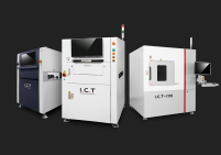
Detection closes the loop. SPI catches paste-volume and print-geometry problems before reflow, exactly when a shift-causing deposit is still cheap to fix. AOI after reflow catches the shifted part itself, but by then it is a scrap or rework event. The stronger play is to use SPI trend data as early warning and AOI data as confirmation the fix held. X-ray is rarely needed for shifting because the defect is visible, but it helps if a shift is paired with a hidden open or a lifted termination.
Prevention is the part that pays back longest. A shifting problem that is fixed once but not controlled will return with the next paste lot, the next stencil, or the next night shift. The strategy is to build the checks into the routine and to choose equipment that makes the balance easier to hold.
Most shifting is prevented by a short list of routine checks: confirm placement accuracy on first article, confirm paste deposit volume and shape with SPI or height checks, keep stencil cleaning on schedule, verify rail seating and conveyor condition at shift start, and confirm the recipe and conveyor speed after any changeover. None of these is expensive. A line that does these checks rarely sees shifting become a chronic problem.
Statistical process control is the durable answer to shifting because it trends the variables that cause it instead of judging pass or fail at a threshold. SPC on paste thickness and placement accuracy, paired with a documented thermal profile, gives you the early warning that a drift is approaching the recoverable limit before any board shifts. The data does not need to be elaborate; what matters is that readings are taken at the same points, recorded the same way, and watched for trend. Component alignment acceptance is framed by the IPC-A-610 assembly acceptability standard (see IPC-A-610 at ipc.org), which sets how much displacement is allowable for a given product class.
Equipment choice shapes how much shifting you fight, because oven airflow uniformity, board support, and transfer smoothness are built into the machine. A chamber with well-controlled, uniform convection gives a smaller directional push on light parts, and a board-support option keeps thin panels from flexing during the molten window. Where fine-pitch and lead-free products dominate, a machine built for zoning flexibility and consistent convection pays for itself in fewer marginal joints and less profile tuning. For a view of how the configurations are positioned, our overview of SMT reflow oven solutions groups them by application and process window.
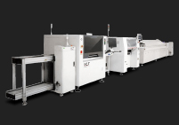
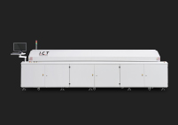
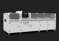
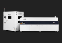
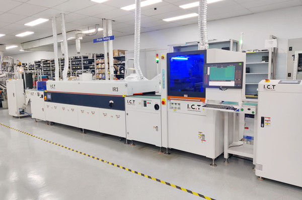
The practical question in any equipment decision is whether the machine's strengths match your product mix, not which specification sheet is longest. I.C.T supplies complete SMT turnkey lines, including the Lyra 622, 733, and 933 reflow series with their multi-zone preheat and peak configurations, plus vacuum, nitrogen, vertical, and board-support reflow options. The Lyra733N modular hot air reflow oven, with PC and Siemens PLC control, optional nitrogen, and an updated cooling zone, is built for the zoning flexibility that keeps the force balance steady. If you are chasing a persistent shifting problem, having process engineers review your placement data, paste deposit, and profile together is usually faster than changing settings blind.
Q: What is the difference between component shifting and tombstoning? A: Shifting is a lateral or rotational move of the whole part off its pad, while tombstoning is a small chip standing upright on one termination because one end wets and pulls before the other. They share some causes, such as asymmetric wetting and placement offset, but tombstoning is driven by a two-sided heat and wetting race rather than by a net sideways force. The heat-balance side of that failure is covered in our article on preventing tombstoning in reflow.
Q: Can the reflow profile alone fix component shifting? A: Rarely. Shifting is mostly caused by placement offset, paste volume, conveyor vibration, and convection airflow, none of which a temperature change directly addresses. The profile matters for confirming that reflow occurred correctly, but if you move peak temperature or time above liquidus within a reasonable range and the shift rate does not move, the cause is mechanical or material. Reach for the placement data, the stencil condition, and the conveyor before the recipe.
Q: Why do only the small components on my board shift? A: Small parts have a low component-mass-to-pad-area ratio, so the same net force that leaves a large package unmoved will slide a tiny capacitor or resistor. They also sit on a thinner, more easily disturbed solder film. When a new small-case-size part is introduced, shift risk rises unless placement accuracy and paste volume are tightened to match. Sort your defect data by component type and you will usually see the shift concentrated where the mass-to-area ratio is lowest.
Q: How much placement offset can self-alignment recover? A: A commonly cited practical limit is roughly half a pad width of offset, but that is a rule of thumb rather than a guaranteed value, because it depends on pad geometry, deposit volume, and how symmetrically the part wets. The safe habit is to treat any offset approaching that range as a defect risk and to keep placement tight rather than relying on the solder to fix it. A part that is rotated or tilted as placed may not center at all, regardless of offset distance.
Q: Does nitrogen reflow prevent shifting? A: Nitrogen mainly improves wetting and reduces oxidation during the molten window, which can help self-alignment recover small offsets, but it does not stop a part from being pushed by airflow or vibration. If the atmosphere system adds a new directional flow disturbance, it could even make matters worse. Treat nitrogen as a wetting aid, not as a shift cure, and keep the airflow itself calm and uniform.
Q: What is the cheapest first check when I see a shifted part? A: Pull the placement deviation data for that component type and check the paste deposit volume and shape with SPI or height checks before you profile the oven. Those checks are cheap, and shifting is far more often a placement or print problem than a thermal one. Only move to a full board profile and conveyor inspection after those cheaper checks have cleared, which keeps you from spending money on an expensive test for a cheap cause.
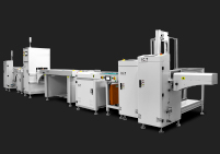
I.C.T supplies complete SMT turnkey lines, including multi-zone reflow ovens, stencil printers, SPI and AOI systems, and factory planning with installation, training, and overseas on-site technical support. If you are working through a persistent component shifting problem and want a second opinion on the process or the equipment configuration, our process engineers are happy to review your placement data, paste deposits, and profile traces with you.