English
Views: 0 Author: I.C.T Publish Time: 2025-07-21 Origin: Site


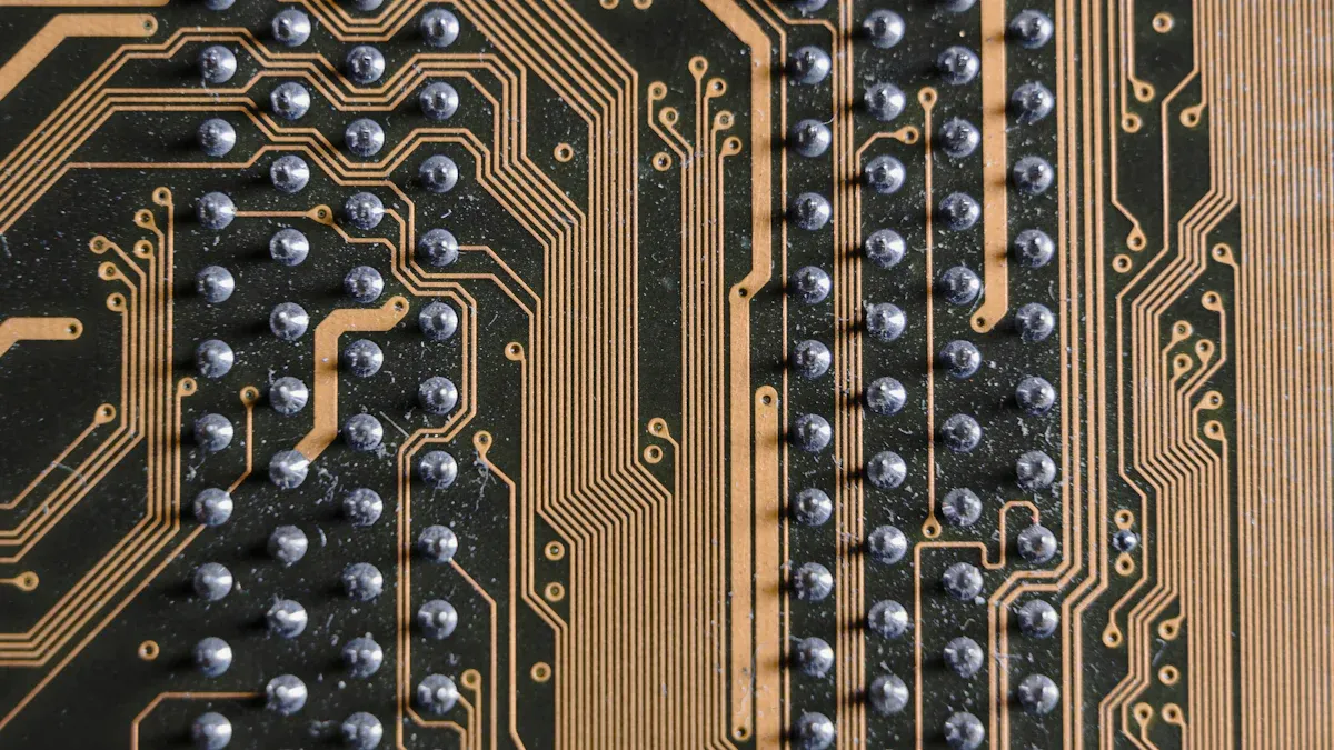
Image Source: pexels
Yes, reflow soldering is safe for flexible PCBs if you use the right steps. Flexible printed circuit boards can be tricky during reflow. Their materials soak up water. This water can heat up fast and make the layers come apart. Some common problems are:
· Water stuck in the PCB can make it bend or break apart when soldering.
· Thick coverlayers can make glue soft, which puts more stress on the layers.
· Baking the boards first and keeping them dry can stop these problems.
Engineers at SMT Oven Factory say to use the right reflow oven. They also say to follow strict quality checks for good surface mount soldering.
· Reflow soldering is safe for flexible PCBs if you watch the heat and follow the right steps.
· Always bake flexible PCBs before soldering to get rid of moisture and stop layer damage.
· Pick materials like polyimide or LCP because they handle heat well and keep the board bendy.
· Use support fixtures and carrier boards to keep flexible PCBs flat and stop them from bending during soldering.
· Set slow heating and cooling speeds to lower thermal stress and stop cracks or warping.
· Choose solder pastes with lower melting points to protect soft flexible PCB materials.
· Check solder joints closely using AOI, X-ray, and by looking to find problems early.
· Use convection ovens and nitrogen atmosphere if you can for even heating and better solder quality.
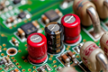
Flexible PCBs are made with special materials. These materials react to heat in different ways. The boards have copper circuits, flex cores, and coverlays. Each layer can only take a certain amount of heat. Some flex cores use glue and can break down if it gets too hot. Flex cores without glue can handle heat better. Polyimide is a coverlay that can take very high heat. But glue and bonding agents may not handle as much heat. Stiffeners and pressure-sensitive adhesives also have heat limits. If the heat goes too high, the PCB can come apart or get damaged. Picking the right materials helps stop damage during reflow.
Tip: Always look at the temperature ratings for every material in the PCB stack-up before you start soldering.
Flexible PCBs are thin and easy to bend. This makes them more likely to get hurt by stress during and after soldering. Bending the board many times can make solder joints weak and cause cracks. How thick the board is and how big the solder pads are both matter. Thinner boards last longer when bent. Smaller pads help the joints last longer too. Rolled-annealed copper for traces and stiffeners in important spots help the board survive bending. The table below shows how design choices change solder joint strength:
Parameter | Effect on Fatigue Life |
Board Thickness | Thinner boards last twice as long under flexing |
Pad Size | Smaller pads improve fatigue life by 25% |
Giving the board good support during soldering and being careful after helps keep the flexible PCB strong.
Flexible PCBs are often used in tough places where they must work well. What the board needs to do changes how you solder it. If you do not control the heat, the board can bend or come apart. Solder joints can get holes or bridges and stop working. Leftover flux and dirt can lower insulation and cause safety problems. Putting parts in the right place and having a good layout lowers the chance of mistakes. Checks like Automated Optical Inspection (AOI) and X-ray help find problems early. Teams need to work together to set the right reflow heat, pick the best solder paste, and clean the board well. These steps help flexible PCBs work well in modern electronics.
Note: Wear safety gear, make sure there is good airflow, and handle solder waste safely to keep workers safe during soldering.
Image Source: unsplash
Flexible PCBs use different substrate materials. Each one reacts to heat in its own way. The most common substrates are:
· Polyimide: This is the top choice for flexible pcb making. It can handle heat up to 260 °C. Polyimide stays flexible and works for many reflow cycles. But it can soak up water, which causes trouble in wet places.
· Polyester (PET): PET is cheaper and used for simple jobs. It only handles heat up to 120 °C. PET does not do well with high heat, so it is not good for hard jobs.
· Liquid Crystal Polymer (LCP): LCP can take heat up to 200 °C. It does not soak up much water and keeps its shape well. LCP is picked for high-frequency circuits, but it costs more.
· PTFE (Fluoropolymer): PTFE can take heat up to 250 °C and fights off chemicals. It is used for special, high-frequency jobs and is pricey.
Tip: Polyimide and LCP work best for reflow soldering. PET can get hurt by high heat.
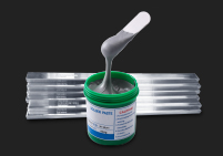
Flexible pcbs need solder pastes that melt at lower heat. Makers add indium or bismuth to tin solder to lower the melting point. Picking the right flux and using heat carefully stops damage during reflow.
How thick a flexible pcb is changes how it acts in reflow soldering. Thin boards bend easily and fit in small spaces. They cool down fast after soldering. But very thin boards can bend or wrinkle if not held flat in the oven.
Most flexible pcbs are between 0.05 mm and 0.3 mm thick. Thicker boards are stronger but bend less. Designers must pick the right balance for the job. Special holders in the oven keep the board flat and stop warping.
Thickness (mm) | Flexibility | Risk of Warping |
0.05 | High | High |
0.15 | Medium | Medium |
0.30 | Low | Low |
The solder mask keeps the pcb safe and controls where solder goes. For flexible pcbs, engineers like Non-Solder-Mask-Defined (NSMD) pads. NSMD pads make solder joints stronger and pad sizes more exact, which helps with tiny parts.
Laser Direct Imaging (LDI) solder mask is more accurate than Liquid Photo Imageable (LPI) masks. LDI is best for small and chip-size parts. A good solder mask sticks well and stops layers from peeling apart, which is a big problem in flexible circuits.
Note: Mixing Solder-Mask-Defined (SMD) and NSMD pads can cause pads to not line up and make bad solder joints. Always match solder mask holes to pad sizes to stop problems like bridging and solder balls.
The right solder mask and design help the board stay strong during reflow. Following IPC-SM-840D rules keeps the solder mask from causing damage or defects.
Thermal stress is a big risk during reflow soldering of flexible PCBs. When the board heats up fast, the materials inside expand at different speeds. This makes stress between copper, resin, and glue. Over time, this stress can make cracks in solder joints or the board. Cracks in solder joints start very small. Heating and cooling again and again makes these cracks bigger. If the cracks grow, the board can break or layers can peel apart.
Studies show lead-free solder joints are stiffer than old ones. This means they push more stress onto the board. This can make the board crack near the solder joints. Sometimes, the board cracks before the solder joints break. This can make it look like the solder joints last longer than they do. Engineers use computer models to guess where damage will start. These models help make better designs and stop failures.
Failure Mechanism | Cause and Description | Impact on Flexible PCBs Failure Rates |
Solder Joint Cracking | Thermal stress from mismatched CTE causes fatigue cracking; alternating stress during thermal cycling initiates cracks; microscopic grain coarsening and grain boundary holes lead to crack propagation. | Leads to solder joint fracture and delamination, increasing failure rates. |
PCB Substrate Cracking | CTE mismatch between resin and copper foil during reflow causes inconsistent expansion; tensile stress and deformation occur in PCB substrate resin. | Causes substrate cracking, contributing to mechanical failure. |
Skin Debonding | High temperatures cause adhesive aging and viscosity loss; elastic/plastic deformation abilities decrease; differing CTEs among skin, film, and PCB increase internal stress. | Results in skin debonding, further weakening PCB integrity. |
SMT Process Defects | Defects such as voids, virtual welding, and pad-diode mismatch exacerbate failure risk during manufacturing. | Necessitates SMT process optimization to reduce failures. |
Failure Rates | Open-circuit failures reached 28.1%, short-circuit 2.72% mainly above 210 °C; failures mainly due to solder joint breakage from excess temperature. | High-temperature reflow soldering significantly increases failure rates. |
Tip: Lowering the highest temperature and heating or cooling slowly helps lower thermal stress and makes the board last longer.
Warping happens a lot during reflow, mostly for thin or big flexible PCBs. When the board gets hot, copper and the base material expand differently. This can make the board bend or twist. Thin boards, like those from 0.6 mm to 1.0 mm, bend more easily. Big boards also bend more because they are hard to hold flat. Materials with low glass transition temperature (Tg) get soft sooner, which makes warping worse.
Many things can make warping worse:
1. Fast temperature changes in the oven put stress on the board.
2. Uneven copper or bad design adds more stress inside.
3. Too many V-cuts or uneven copper layers make the board weak.
4. If the board has water in it, it can swell and bend when heated.
5. Heavy parts or no support during soldering can bend the board.
Using high Tg materials, even copper layers, and thicker boards helps stop warping. Cooling the board slowly after soldering also helps. Oven trays or special holders keep the board flat during reflow.
Note: Good support and careful control of the process are important to stop warping in flexible PCBs.
Delamination is when layers inside the pcb pull apart during reflow soldering. This happens more if the board has soaked up water before soldering. When the board heats up, water turns to steam and pushes the layers apart. This can make bubbles, blisters, or even full layer splits. If the materials inside expand at different rates, this can also cause delamination.
Other reasons for delamination are bad lamination during making, too much heat, fast temperature changes, or stress from drilling or handling. If the lamination does not use enough pressure or vacuum, the glue between resin and copper is weak. This makes the board more likely to come apart during reflow.
Cause | Explanation |
Moisture Absorption | Moisture absorbed during storage or processing vaporizes during soldering, creating vapor pressure that separates layers. |
Thermal Expansion Mismatch (CTE) | Differences in thermal expansion between copper, resin, and metal base generate internal stresses during temperature cycling, causing separation. |
Poor Lamination Process | Insufficient lamination pressure or vacuum leads to weak bonding between resin and copper, making layers prone to delamination during reflow. |
Excessive Heat or Thermal Shock | Rapid heating or cooling during soldering can exceed material limits, causing bubbling, blistering, or layer separation. |
Mechanical Drilling Stress | Improper drilling parameters can introduce mechanical stress that fractures resin bonds, contributing to delamination. |
Keeping PCBs dry and baking them before soldering helps remove water and lowers the chance of delamination. Controlling the reflow process and not heating or cooling too fast also keeps the board strong.
Solder joint issues are a big problem when making flexible PCBs with reflow soldering. These problems can make the electrical connections weak. This means the finished product may not work well. Flexible circuits have thin layers and special materials. These can react in different ways to heat and movement.
The most common solder joint defects in flexible PCB manufacturing include:
Defect Type | Manifestation in Flexible PCBs After Reflow | Common Causes |
Solder Bridging | Unintended solder connections between adjacent pads | Excess solder paste, improper stencil design, component misalignment |
Tombstoning | Component standing vertically on one end | Uneven heating, pad size discrepancy, insufficient solder paste |
Solder Balling | Small solder beads on PCB surface or near joints | Moisture in solder paste, excessive paste, inadequate reflow profile |
Insufficient Solder | Weak or dry joints, incomplete solder coverage | Poor solder paste application, PCB surface finish issues |
Cracked Components | Physical damage to components due to thermal stress | Too rapid heating, moisture expansion inside components |
Delamination | Separation of PCB layers due to moisture or heat | Moisture trapped in PCB material, improper storage or baking |
These defects can show up in different ways. Solder Bridging happens when extra solder connects two pads or leads. This can make a short circuit and hurt the pcb. Tombstoning is when a small part stands up on one end after reflow. This happens if one side gets hotter or has more solder. Solder Balling means tiny balls of solder appear on the board or near joints. These balls can move and cause shorts if not cleaned off. Insufficient Solder makes joints look thin or dry. These joints may not hold parts well or carry electricity. Cracked Components happen if the board heats up too fast or if water inside the parts expands. Delamination is when layers inside the pcb pull apart. This can happen if the board is wet or not baked right.
Solder joint issues often come from not controlling the reflow process well. Mistakes in getting ready for soldering can also cause problems. Flexible pcbs need careful handling because their materials soak up water. If the board is wet, steam can form during reflow. This can make solder balls or delamination. Uneven heating or too much solder paste can cause bridging and tombstoning.
To lower these risks, engineers use careful reflow profiles and control the solder paste amount. They check each board after soldering to find problems early. Good storage and baking keep water out of the materials. By doing these things, makers can make flexible pcbs that work better and last longer.
Tip: Always look for solder joint problems after reflow. Finding them early helps stop failures in the final product.

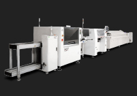
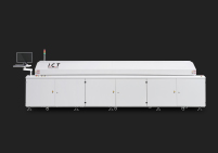
Convection reflow ovens use moving hot air or gas to heat flexible PCBs. This method gives even heat to every part of the board. The air flows around all surfaces, so each component reaches the right temperature at the same time. This helps avoid hot spots and cold areas. When the heat is even, solder paste melts smoothly and solvents can escape. This lowers the chance of voids and weak solder joints.
Many factories use a conveyor to move boards through the solder reflow oven. The conveyor keeps the boards flat and steady. Multi-zone convection ovens let engineers set different temperatures in each zone. This helps control the heating and cooling steps for flexible PCBs. Convection ovens also work well with nitrogen, which improves solder quality.
Tip: Convection ovens are the top choice for flexible PCB soldering because they give the best temperature control and reduce defects.
Infrared reflow ovens use radiant heat to warm up the PCB. The heat comes from special lamps and travels in straight lines. This can cause problems for flexible PCBs. Some parts may get too hot while others stay cool. The board material and color can change how much heat it absorbs. This uneven heating can make hot spots, cold zones, or even warping.
IR ovens can heat up quickly, but the fast and uneven heat may trap gases in the solder paste. This can lead to more voids and weaker solder joints. Flexible PCBs need gentle and even heating, so IR ovens are not the best fit. Factories that use a conveyor with IR ovens must watch for bending or twisting as the board moves through the heat.
Oven Type | Heating Method | Temperature Uniformity | Defect Risk for Flex PCBs |
Convection Oven | Circulating Hot Air | High | Low |
IR Oven | Radiant Heat | Low | High |
A nitrogen atmosphere in a solder reflow oven helps make better solder joints. Nitrogen is an inert gas that pushes out oxygen and moisture. This stops oxidation during reflow. Less oxidation means the solder flows better and sticks well to pads and leads. Nitrogen also lowers the surface tension of solder, so it spreads out and covers pads more evenly.
Using nitrogen lets engineers pick from more types of flux. It can also cut down on cleaning after soldering. The process window gets wider, so the line can run faster with fewer defects. Nitrogen is very helpful for tough jobs like lead-free soldering or boards with tricky parts. The main downside is the extra cost for nitrogen, but the gains in quality and yield often make it worth it.
Note: Nitrogen atmospheres help reduce solder balls, bridging, and poor wetting. This leads to stronger, more reliable flexible PCBs.
The ramp-up step slowly heats the flexible PCB. This is important to protect the board’s materials. Flexible PCBs often use polyimide. Polyimide does not handle heat as well as hard boards. Heating too fast can hurt the board. A slow ramp-up, about 1–2°C per second, is best. This helps stop thermal shock. If you heat too quickly, the board can bend or layers can split. Sometimes, the board can even burn. By heating slowly, engineers keep the board safe and steady.
Tip: Always heat up the board slowly. This stops sudden temperature jumps and keeps the flexible PCB safe during reflow.
After ramp-up, the soak step gets the board ready for soldering. The temperature stays between 120°C and 160°C for 60 to 100 seconds. This lets the whole board warm up evenly. The soak also wakes up the flux in the solder paste. Flux helps clean metal parts so solder sticks better. Even heating in this step stops problems like voids or solder bridges.
Parameter | Value/Range | Purpose/Notes |
Soak Temperature | 120°C to 160°C | Makes sure the board heats evenly and flux works |
Soak Time | 60 to 100 seconds | Stops overheating and lowers the chance of splatter or rust |
A good soak step is key for flexible PCBs. It makes sure the flux works but does not let the board get too hot.
The peak temperature step is when the solder melts and makes connections. Flexible PCBs need lower peak heat than hard boards. Most flex boards use a peak between 215°C and 260°C. Hard boards can take more heat, sometimes over 260°C. Flex materials like polyimide cannot take that much. Too much heat can make the board bend, split, or break parts.
Aspect | Rigid PCBs | Flexible PCBs |
Peak Reflow Temperature | Up to 260°C or higher | 215°C to 260°C (lower peak) |
Process Control | Standard profiling | Needs tighter and careful control |
Engineers use special tools to watch the heat closely. They often only let flexible PCBs go through reflow once. This stops the material from getting too stressed. Keeping the peak temperature just right makes strong solder joints and keeps the board safe.
Note: Setting the right heat steps for flexible PCBs keeps them safe and helps them last longer.
The cooling step is very important for flexible PCB boards. After the solder gets hot, the board needs to cool down slowly. This helps the solder joints form well and keeps the board flat. If the board cools too fast, it can bend or crack. Engineers watch this step closely because quick cooling can hurt flexible PCBs.
Cooling slowly lets the solder harden the right way. If the board cools too quickly, the different parts shrink at different speeds. This puts stress between the copper, the base, and the solder. The board can bend, and parts might move out of place. Sometimes, fast cooling can even make the board layers split or parts break.
If you cool the board too fast after soldering, it can cause too much stress. This can make the layers come apart or parts crack. So, it is important to cool the board at the right speed to stop these problems.
Makers usually cool flexible PCBs at 2°C to 4°C per second. This speed lets the solder get hard without trapping stress inside. Slower cooling also stops the solder from getting too hard and breaking later. Flexible PCBs need this care because their thin layers and glue change more with heat than hard boards.
The materials in the board also change how it cools. Some materials do not shrink much, so the board stays flat. Engineers sometimes use trays or holders to keep the board flat while it cools. These tools stop the board from bending or twisting as it gets cold.
Studies show that boards bend more if they cool too fast. Cracks in the solder or parts moving out of place happen more often. By picking the best cooling speed, makers can stop these problems and help the board last longer.
Cooling the board the right way after soldering keeps it strong. It also makes sure the solder joints stay good for a long time.
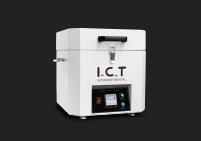
Pre-baking is a very important step before reflow soldering flexible PCBs. Flexible boards can soak up water while being made or stored. This water can cause layers to peel, bubbles, or bad solder joints when the board gets hot in the oven. Experts say to bake flexible PCBs at 100°C to 125°C for 4 to 16 hours. This heat is not too high, so it keeps the board safe.
A forced-air oven spreads heat evenly. Workers should put boards on clean trays or racks with space between them. Stacking boards no higher than 25.4 mm helps each board get the same heat. After baking, let the boards cool in a dry place. Store baked boards in special bags with drying packs and cards that show if it is dry. This keeps the boards dry until they are used.
Baking flexible PCBs before reflow gets rid of water. This lowers the chance of bubbles, cracks, and bad solder joints.
A normal pre-baking process has these steps:
1. Look at the maker’s rules for baking time and heat.
2. Heat the oven to the right temperature.
3. Put PCBs on trays with space between each one.
4. Bake for the right amount of time.
5. Let boards cool in a dry spot.
6. Store in special bags with drying packs.
Doing these steps makes the boards work better and helps stop hidden problems during reflow.
Fixation stops flexible PCBs from moving or bending during reflow. Flexible boards can shift or sag as they move through the oven. This can make parts not line up or cause bad soldering. Engineers use different ways to keep boards still.
· Clips or pins go in holes to hold the PCB in place.
· Carrier boards support the flexible PCB and keep it flat.
· The right amount of force is important. Too much can shake the board and knock off parts.
· After reflow, take the PCB off the carrier board gently to avoid damage.
A good fixation system works with the oven’s conveyor to keep the board lined up from start to finish. This helps make sure the boards are made well every time.
Using a good carrier board and gentle holding methods helps stop problems and keeps flexible PCBs in good shape.
Storing flexible PCBs and solder paste the right way is very important for good soldering. Boards and materials can soak up water if left in damp air. This water can turn to steam in the oven and cause solder balls, bubbles, or splatter. These problems can make short circuits or weak solder joints.
To stop these problems, workers should:
· Keep flexible PCBs in special bags with drying packs.
· Use cards that show if it is dry inside the bag.
· Keep solder paste closed and cold as the maker says.
· Do not leave boards out of storage too long before soldering.
If boards or solder paste get wet, baking and careful heating in the oven are even more important. These steps help dry out water and lower the chance of problems during reflow.
Good storage keeps flexible PCBs safe and helps make sure every board works well during assembly.
Support fixtures are very important for flexible PCBs during reflow soldering. Flexible boards can bend or twist when they get hot. This can make parts move or solder joints break. Engineers use support fixtures to stop these problems. They help each board stay flat and strong.
The most common support fixtures are called stiffeners. Stiffeners make certain areas stronger, like where connectors or heavy parts go. They help the board stay flat and keep all the parts in place. Makers often put stiffeners on just for reflow. This stops the board from bending or parts from moving.
Stiffener Material | Use Case / Function |
FR4 | General applications needing rigidity |
Aluminum | Lightweight, high-strength requirements |
Polyimide | Flexible yet supportive areas |
Stiffeners can be made from different things. FR4 is good for most jobs that need more strength. Aluminum is light and very strong, so it is good for boards that must not be heavy. Polyimide gives some support but still lets the board bend a bit. Engineers choose the stiffener based on what the board needs.
Support fixtures do more than just make the board stronger. They help in many ways: They keep the board flat when it heats up or cools down. They stop connectors and heavy parts from pulling the board out of shape. They help all the parts line up for good solder joints. They lower the chance of the board bending, warping, or cracking.
Studies show that using stiffeners and other support fixtures helps a lot. Boards with the right fixtures stay flat and have fewer problems after soldering. Research by Lall and Muhammad proved this. Their work shows that support fixtures are very important for making flexible PCBs that work well.
Tip: Always pick the best support fixture for each board. This helps stop defects and keeps the finished product strong.
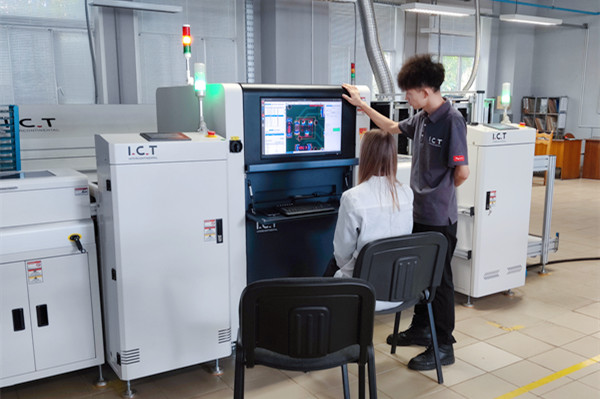
Inspection is very important for making sure flexible PCB assemblies work well after reflow. There are rules like IPC J-STD-001 and IPC-A-610 that tell how to check the boards. These rules explain what materials to use and how to look for problems. They help engineers find things like cold solder joints, solder bridges, and parts that are not in the right place.
There are different ways to check for problems early:
· Automated Optical Inspection (AOI): Special cameras look at the board to find surface problems, missing parts, or wrong part direction.
· Solder Paste Inspection (SPI): This checks if the right amount of solder paste is in the right spot before putting on parts.
· X-ray Inspection: X-rays can see under parts like BGAs and QFNs to find hidden problems, like empty spots or solder balls that are not lined up.
· Visual Inspection: Magnifying tools help people see cracks, bridges, or bad solder joints after soldering.
Using all these ways together works best. AOI and SPI find most problems you can see on top. X-ray finds problems you cannot see. Looking with your eyes helps catch anything missed. These steps help stop common reflow problems in flexible PCBs.
Tip: Checking early helps avoid expensive fixes and makes the product last longer.
Testing makes sure the solder joints and the whole board work right after reflow. Engineers use many tests to check if the board is strong and does its job.
· Solderability Testing: This test checks if pads and leads make strong solder joints so there are no weak spots.
· Microsection Analysis: Engineers cut the board and look at it under a microscope to find empty spaces or layers coming apart.
· Flying Probe Testing: Moving probes check for open circuits or wrong values, which is good for small numbers of boards.
· Aging (Burn-in) Testing: Boards run hot for a while to see if they will last a long time.
· Hot Oil Test: Boards go into hot oil to see if they can handle heat stress.
· In-Circuit Testing (ICT): Special tools check if all the parts and connections work in big batches.
· Functional Testing (FCT): This test acts like real use to make sure the board works as it should.
· Thermal Imaging: Infrared cameras look for hot spots that might mean a bad connection.
Engineers also use tests like heating and cooling or shaking the board to see if the solder joints stay strong. These tests, plus checking the heat profile, help make sure every board is good.
Flexible PCBs sometimes go through more than one reflow cycle, especially for hard builds. Each time the board goes through reflow, it gets more stress. Too many cycles can make the board layers come apart, bend, or crack the joints. Watching the heat closely each time helps lower these risks.
The rules say to count how many times the board goes through reflow and check it after each time. Engineers often put a special coating on the board to keep out water and protect it from more stress. They also check and test the board after every reflow to find damage early.
Note: Keeping the number of reflow cycles low and using careful heat control helps flexible PCBs stay strong and work well.
Reflow soldering is safe for flexible PCBs if you use the right steps and tools. Industry examples show some important things to do:
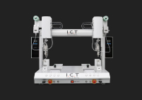
1. Special reflow ovens and tools help keep the heat even and hold parts still.
2. Picking good materials and planning the circuit well helps stop stress and keeps the board from bending.
3. Setting the right heat steps protects the board and makes strong solder joints.
4. Using the right amount of solder paste and checking the boards carefully helps find problems early.
If teams follow these steps and check their work closely, they can make flexible PCBs that work well every time.
Water in the board can turn into steam when heated. This steam can make layers come apart or cause bubbles. It can also make solder joints weak. Baking the board and storing it right helps stop these problems.
Yes, engineers use lead-free solder for flexible PCBs. Lead-free solder melts at higher heat. So, you must watch the oven temperature closely. This keeps the board safe from damage.
Most flexible PCBs can go through one or two reflow cycles. Each time adds heat stress to the board. Too many cycles can make the board bend or crack. Layers may also come apart.
Support fixtures hold the flexible PCB flat in the oven. They stop the board from bending or twisting. This keeps all the parts lined up during heating and cooling.
Engineers usually bake flexible PCBs at 100°C to 125°C. They do this for 4 to 16 hours. Baking gets rid of water and lowers the chance of problems during soldering.
Yes, flexible PCBs often use solder paste that melts at lower heat. This protects the board from getting too hot. It also helps make strong solder joints.
Engineers use AOI, X-ray, and visual checks. These ways help find problems like solder bridges or missing parts after soldering.
You do not have to use nitrogen, but it helps. Nitrogen makes solder joints stronger and lowers defects. It is very helpful for tricky or lead-free boards.