English
Views: 0 Author: I.C.T Publish Time: 2025-07-18 Origin: Site


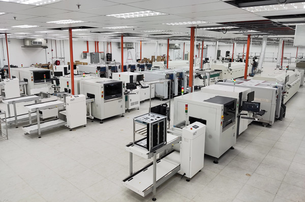
To prevent voids in BGA soldering when using equipment from a reflow oven manufacturer in China, it’s important to set an accurate reflow profile. Choose high-quality solder paste and control moisture levels carefully. Always follow best practices for material handling and process management. In modern electronics factories, voids in BGA solder joints are typically kept below 25% to ensure reliable performance. Large or clustered voids can weaken solder joints and reduce their lifespan, especially during BGA soldering in the reflow process. It’s crucial to monitor every step closely, as the location and size of voids can impact both the quality and durability of your soldering. Many reflow oven manufacturers in China now offer advanced solutions to help minimize voids during BGA soldering.
· Set the reflow profile with the right heat and time. This helps lower voids and makes strong solder joints. Use good solder paste and handle it the right way. This stops gases and water from getting trapped and causing voids. Design stencils so gases can escape during soldering. This helps stop big voids under the BGA. Keep humidity low and bake parts before soldering. This removes water and keeps joints from cracking. Check solder joints with X-ray tools to find hidden voids. Keep void levels below the suggested limits for better reliability.
When you do BGA soldering, you must watch for voids. Voids are tiny pockets of gas or flux inside the solder joint. These voids can make the joint weaker and cause it to fail later. Solder joint voiding makes it harder for the joint to move heat and electricity. If you ignore bga solder voids, your device might not work well or could stop working. Many electronics makers set strict rules for voiding to keep things reliable. You should always try to stop voids and keep solder joint voids under the allowed limit.
Tip: Check your work often to find bga solder voids early and stop common bga defects.
You can stop voids better if you know how they happen. Bga solder voids usually start during the reflow process. When the solder melts, it tries to stick to the pad and the solder paste. Sometimes, the flux in the paste gets trapped if the outside of the bump sticks faster than the inside. This trapped flux turns into vapor and builds up pressure, but the solder may not stay melted long enough for the vapor to get out. This makes bga solder voids inside the joint.
The main reasons for voids are:
1. Solder paste printing mistakes that put too much or too little paste on the pad.
2. Bad reflow oven profiles that do not give enough time for gases to leave.
3. Using solder pastes with high boiling point fluxes that trap vapor.
4. Dirty parts or PCBs that stop the solder from sticking right.
5. Not storing or handling solder paste right, which changes it and causes more voids.
You can lower voids by fixing your reflow profile, picking low-voiding solder pastes, and keeping your process clean. Many experts say to use a slow temperature ramp and a longer soak time. For lead-free bga soldering, you should aim for a peak temperature of about 245°C for boards with parts on them. Vacuum-assisted reflow can also help you stop voids by pulling out trapped gases. Always check your process and materials to keep bga solder voids low and make joints last longer.
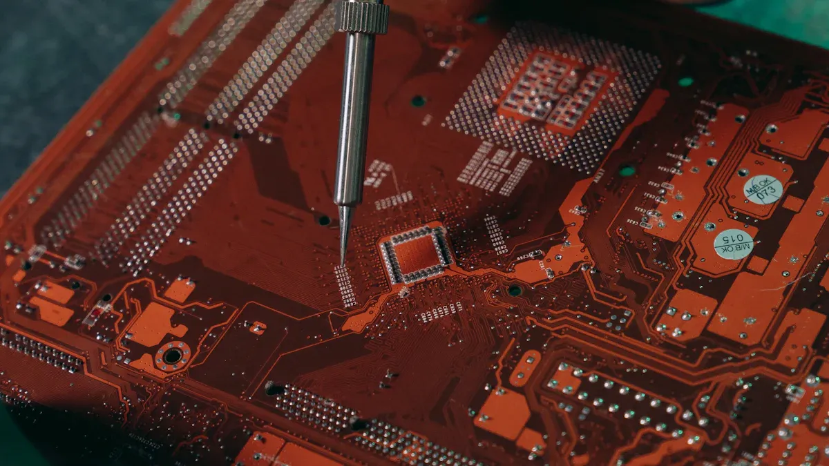
Image Source: pexels
Making your reflow profile better is a great way to lower solder joint voiding in BGA assemblies. You have to watch the temperature, time, and air during reflow soldering. This helps you get strong and reliable joints. If you change the reflow temperature settings carefully, you can get fewer voids and make your process more steady.
You need to pick the right temperature for each step in reflow soldering. Start with a slow ramp rate, about 1°C to 3°C per second. This keeps the board safe from thermal shock and lets gases leave. Most makers say to use a ramp rate of 1–2°C/s for small solder paste or fine-pitch BGAs. This helps stop problems like solder balling and tombstoning.
In the soak phase, keep the temperature between 155°C and 185°C for 30 to 120 seconds. This lets the board and parts heat up evenly. But if you soak too long or too hot, you can get more oxidation and voids. For the peak phase, set the temperature between 230°C and 245°C for lead-free soldering. Make sure the peak is at least 15°C higher than the solder’s melting point. Hold this for 45 seconds or more. This helps the solder stick well and lets gases escape.
Tip: Put thermocouples in different places on the BGA and PCB. This helps you check the heat and lowers the chance of solder joint voiding.
Time is very important in reflow soldering. The time above liquidus (TAL) matters most for making the flux work and lowering voids. Try to keep TAL between 60 and 90 seconds. This gives the flux time to clean off oxides and lets gases get out before the solder hardens.
Don’t rush the steps. If you go too fast in the ramp or soak, you trap gases inside the joint. If you make the soak or peak last too long, you might hurt sensitive parts or cause other problems. You need to watch the time at each step and sometimes try different ways. Many experts say that making the profile perfect takes practice, but these tips will help you get good results.
The air inside your reflow oven is important for solder joint quality. Nitrogen gas pushes out oxygen and stops oxidation. This makes cleaner and stronger solder joints. Nitrogen also helps the solder spread and lowers the number of voids in BGA and fine-pitch assemblies.
Benefit | Impact on BGA/Fine-Pitch Assemblies |
Reduced oxidation | Nitrogen stops oxides, so there are fewer empty spots and bridges. |
Improved solder wetting | Inert air helps solder spread, which is key for BGA parts. |
Lower void rate | Better solder flow means fewer voids, so electrical work and reliability get better. |
Lower reflow temperature | You can solder at lower heat, which protects parts and lowers void risks. |
Formic acid vapor is another way to lower voids during reflow soldering. If you use formic acid in a vacuum reflow oven, you make a reducing air that cleans oxides from parts, solder joints, and PCB surfaces. This helps the solder stick better and makes fewer voids. This is very important for advanced BGA packaging. Big industries like aerospace and automotive use this method to meet strict rules for reliability.
Note: Always check oxygen levels and change formic acid and soak times to get the lowest void rates.
If you control temperature, time, and air well, you can lower solder joint voiding and make your BGA assemblies more reliable. Remember, thermal profiling and fine-tuning your process are needed for steady, high-quality reflow soldering.
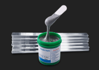
Picking the right solder paste helps stop voids in bga soldering. The paste should have the right mix of solvents. This lets gases get out when you heat it up. It keeps them from getting stuck inside. Good wetting means the paste can clean the pad well. This helps make strong solder balls. If you use a paste with good surface tension, it spreads better and makes fewer voids. The flux should not have too much non-volatile stuff. If there is too much, it can block the solder balls from falling and trap gases. Try to find solder paste with rosin that melts at a low temperature. This helps the flux work well during reflow. Using less rosin than normal lets activators work on time. It also stops the solder balls from sticking together.
Tip: Always read the technical data sheet for your solder paste. The maker will list things that help lower voids in bga soldering.
Storing and handling solder paste the right way keeps bga solder joints safe. Put solder paste in a cool and dry place. Keep parts and PCBs in a clean area to stop dirt and rust. Follow the moisture-sensitive level rules to keep out water problems. Use ESD safety when you touch any materials. When you print solder paste, use good stencils. Make sure the holes match your bga layout. Control how much solder paste you use. It should cover about half to most of the pad. This helps you get the same results each time. Always set your reflow profile to match the solder paste and parts. Using nitrogen in the oven can also help stop rust and lower voids.
Putting solder paste on the same way every time makes bga solder joints strong. Voids can happen when gases leave during reflow. If you use too little solder paste or flux, gases may not get out. This can cause more voids. The type and strength of the flux in your paste matter a lot. If the flux is not strong enough, gases stay inside and make voids. For ceramic bga, you need more solder paste. This is because the package gives less solder than others.
Aspect | Explanation |
Solder Paste Volume Importance | For ceramic bga, enough solder paste makes joints strong. |
Impact of Insufficient Paste | Too little solder paste or flux causes problems and more voids. |
Role of Solder Balls | Some bga use solder balls, but ceramic bga needs extra paste. |
Consequence | Not enough solder paste or flux means weak joints and more voids. |
Note: Always check your solder paste before reflow. Putting it on the same way each time lowers voids and makes bga soldering better.
You must keep moisture away from your bga components before soldering. If water gets inside the solder balls, it can make voids during reflow. If you think your bga parts have moisture, bake them before you use them. Baking takes out the water and helps stop cracks or layers from peeling. Most experts say to bake bga parts at 125°C for 24 hours if they were in the air too long or if you are not sure about storage. Always follow the rules from the maker and groups like IPC and JEDEC. Store your bga parts in special bags with drying packs. Keep the humidity under 40% RH. Do not try to fix moisture damage by baking after reflow. Once damage happens, you cannot undo it. Use X-ray or C-SAM to look for hidden voids or cracks after soldering.
Tip: It is better to stop problems than to fix them. Always bake and store your bga parts the right way before reflow.
You need to keep the humidity low in your work area to stop voids in bga soldering. High humidity can make flux under parts soak up water. This can form films that cause more voids and make joints less strong. If your workspace has small gaps or tight connectors, trapped flux and bad gas flow can make things worse. Keep the room dry and use good airflow to help gases get out during soldering. Better outgassing and smart design, like bigger spaces between parts, also help lower flux and voids. Always check your work area and change things if needed to keep your bga joints strong.
· Moisture can cause:
o Voids inside solder balls or at joints
o Trapped flux gases
o Joints that shrink and crack
o Air pockets from vias
Note: If you follow IPC-610D and IPC-7095A rules, you can keep voids at safe levels.
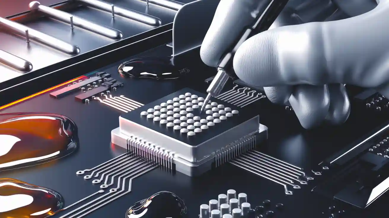
You can lower voids in bga soldering by changing your stencil design. When you print solder paste, you should create paths for gas to escape under the bga. Use patterns like 5-dice, window pane, cross hatch, or radial shapes. These patterns help gases move out before the solder hardens. If you have thermal pads, break up large solder paste areas with crosshatch patterns. This lets trapped gas escape and keeps the joint strong.
· Divide large stencil openings into smaller ones. For example, use four small apertures instead of one big one.
· Make clearances around via holes. This stops solder paste from flowing into vias and causing voids.
· Try a thicker stencil, such as 0.2 mm, but keep the same solder paste volume. This gives more space for gas to escape.
· Use aggressive flux with smaller divided apertures and no solder mask. This method works well and does not add cost.
These changes help you avoid voids and make bga rework easier. You do not need to change your solder paste or reflow profile. You just need to adjust your stencil.
You must place solder balls and solder paste with care during bga rework. If you use too much or too little solder paste, you can get weak joints or extra voids. Always check that the solder balls sit in the right spot on the pads. Use a stencil that matches your bga layout. This helps you get the same amount of solder paste on every pad.
A good placement process helps you avoid cold joints. Cold joints happen when the solder does not melt fully. This can lead to bga rework problems later. You should use a steady hand and the right tools for placing solder balls and solder paste. This keeps your bga joints strong and ready for rework if needed.
Component warping can cause big problems during bga rework. If your bga or the board bends during heating, you may see uneven solder joints or extra voids. Warping can lift some solder balls off the pad, making the joint weak. You should control your reflow temperature and use slow heating to stop warping.
· Store your bga parts flat and dry.
· Use a rework station with even heating.
· Check for warping before and after rework.
If you see warping, you may need to adjust your process or replace the part. Careful handling and the right tools help you avoid rework issues and keep your bga joints reliable.
Vacuum reflow is a special way to get rid of trapped gases. It helps lower voids in solder joints. You put your bga assembly in a reflow oven that makes a vacuum. When the solder melts, the oven pulls air out. This lets gases and flux leave the solder joint. You end up with fewer voids and stronger joints.
You can change how long and how strong the vacuum is. Most ovens use the vacuum right after the solder melts. This lets the solder fill spaces while gases escape. This method works well for bga packages and other parts that need to be very reliable. You will see much less voiding than with normal reflow. Many people get voids under 2% with vacuum reflow. Normal reflow often leaves 10% or more.
Tip: Watch the vacuum cycle closely. Too much vacuum or bad timing can make splatter or uneven joints.
Vacuum reflow is not needed for every job. Use it when you need very low voids or when normal reflow does not work well enough. Studies show vacuum reflow helps most in these cases:
· LED assembly, where almost no voids are needed for good heat flow and long life.
· High-reliability bga soldering, like in cars or planes.
· Projects where normal solder paste and flux do not give low enough voids.
· When you must have voids below 2% for best results.
Vacuum reflow gives better joints, but it costs more and takes more steps. You may work slower and need to train your team more. Experts say you must plan your process well to stop splatter or long cycles.
Benefit | Challenge |
Voiding below 2% | Higher equipment cost |
Stronger solder joints | More process steps |
Better reliability | Slower throughput |
Note: Vacuum reflow is best when your job needs the extra work and cost. For most bga soldering, a good reflow profile may be enough.
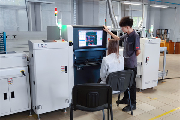
You have to check your joints well to make sure they work. Looking at them helps you find cracks or bumpy solder on the outside. But you cannot see inside the joint with just your eyes. For hidden problems, you need special tools. X-ray inspection lets you look inside the joint. It helps you find voids or cracks that could break the joint. New X-ray machines use smart software to measure voids fast and right. You can even make 3D pictures to see where each problem is.
Here is a table that shows how different inspection methods work:
Inspection Method | Description | Effectiveness for Detecting Voids | Limitations |
Visual/Optical Inspection | Uses cameras or magnifiers for surface checks | Only finds surface defects | Cannot see hidden voids inside joints |
2D X-ray Inspection | Creates 2D images of internal structure | Detects internal voids, but overlaps possible | Overlapping features reduce accuracy |
3D X-ray (CT Scan) | Produces high-resolution 3D images | Most effective for internal voids | Higher cost and advanced equipment needed |
Ultrasonic Inspection | Uses sound waves to check inside | Finds internal voids and delaminations | Less common, needs special equipment |
Destructive Methods | Physically cuts or dyes the joint | Finds voids and cracks | Destroys the sample, not for routine use |
You can see how well these methods work in the chart below:
X-ray inspection is the best way to find and measure voids without breaking the joint. You need trained people or smart programs to read the X-ray pictures. Just looking at the joint is not enough to find hidden voids. Always use both ways to check bga joints well. If you miss a void, you could get a cold solder joint that might break later.
You need to know the rules for how many voids are okay in joints. Most rules say the biggest void area should be less than 25% of the joint, as seen in X-ray pictures. Some new reports say up to 30% is okay in some cases. For important pads, experts say to keep voids under 10% to 25%, depending on where they are.
Criterion Description | Maximum Allowable Void Level | Notes/Source |
Voids should not exceed 20% of solder ball diameter | ≤ 20% of solder ball diameter | Single void on outside not allowed; multiple voids sum ≤ 20% acceptable |
IPC-7095 pad layer void area limit | ≤ 10% of solder ball area (void diameter ≤ 30%) | Void located on pad layer |
IPC-7095 solder layer void area limit | ≤ 25% of solder ball area (void diameter ≤ 50%) | Void located in solder ball center |
General unacceptable void size | > 35% of solder ball diameter | Indicates process-related problem; not accepted |
Voids outside solder joints detected by X-ray | Not acceptable | X-ray inspection required; resolution ≥ 1/10 ball diameter |
You should always check your joints to make sure they follow these limits. If you see voids bigger than one-third of the ball size, you need to fix your process. Keeping voids in the safe range helps stop failures and makes strong, good joints.
You can get good BGA soldering if you control your process and use good materials. Try using smaller stencil holes and less solder paste when you do bga rework. Make the preheat and soak steps longer so flux gases can leave. Always pick high-quality solder paste and set your reflow oven the right way. For bga rework, keep the air dry and think about using vacuum reflow to get the fewest voids. Learn about new solder alloys, better flux, and smart factory tools. If you keep making your rework process better, your joints will stay strong and have fewer voids.
You often see voids because of trapped gases from solder paste flux, poor reflow profiles, or too much moisture. Dirty surfaces and bad stencil design also increase voids. Always check your process and materials to reduce these risks.
You should use X-ray inspection. This tool lets you see inside the solder joints and find hidden voids. Visual checks only show surface problems. X-ray gives you the best results for BGA soldering.
No, you do not always need vacuum reflow. You can often control voids with a good reflow profile and high-quality solder paste. Use vacuum reflow when you need very low voids, such as in automotive or aerospace projects.
Standard | Max Void Area Allowed |
IPC-7095 | 25% of solder ball |
Industry Best | 10–25% of pad area |
You should keep voids below these limits for strong, reliable joints.