English
Views: 0 Author: Vinci Zhang Publish Time: 2026-10-13 Origin: Site


Solder bridging is the defect that most often turns a clean print into a scrap board. It is a short: molten solder joining two adjacent pads, leads, or terminations that should stay separate. The good news is that bridging is almost always decided before the board reaches the oven. This article is a single-defect deep dive for process engineers who need to stop bridges at the source.
The permitted causes behind bridging are a short list: too much solder paste, a stencil aperture or thickness that deposits more than the pad can hold, paste that slumps before it melts, placement pressure that squeezes paste sideways, a reflow ramp that is too fast, and a pad pitch too small to leave a margin. For the wider picture, our complete guide to reflow soldering defects covers the full defect map and diagnostic routine.
One boundary up front. Bridging is a print-and-placement defect that only becomes visible after reflow. If you change the oven profile first, you are starting in the wrong place. Reduce the paste, fix the stencil, and check placement pressure before you touch a zone setting.

The fastest path to fewer bridges is to understand what you are looking at and where it was decided. A bridge is a volume-and-geometry problem that the reflow heat merely exposes, so investigate at the printer rather than the oven.
A solder bridge is an unintended metallic connection between two conductors that should remain separate. On a fine-pitch IC it is a thin web of alloy spanning two leads; on a passive array it is a lump joining two terminations. In every case the joint that should have formed on each pad merged with its neighbor, producing a short that can fail a continuity test or pass test and fail in the field.
The reason bridging matters more than some defects is that it is a hard electrical fault. A dull joint may still conduct; a shifted part may still sit close enough. A bridge is a direct short, and shorts do not get friendlier with time, so detection and prevention deserve a deliberate plan.
Almost every bridge traces back to one of six conditions, and they combine. Excess solder paste is the leading cause because volume is what overflows the gap. A wrong stencil aperture or thickness sets that volume. Paste slump is the time-dependent cause. Excessive placement pressure squeezes deposit sideways. A too-fast reflow ramp pushes paste around through violent outgassing. A too-small pad pitch removes the margin that would absorb a small error.
These are six levers, not six independent problems. The right order is volume first, then stencil, then print stability, then placement, then the profile. The later levers only matter once the earlier ones are stable.
Bridging is invisible at the printer. The deposit sits on each pad, the component is placed, and the board looks clean. Then the alloy melts, the flux activates, and surface tension either pulls each deposit onto its own pad or lets two deposits flow together. The defect was always latent in the volume and geometry; reflow is when it declares itself.
That timing is why teams misdiagnose bridging as a thermal problem. The symptom appears at the oven, so the oven gets blamed. In reality the oven only revealed a print or placement condition present from the first panel.
Bridges are far more common as pad spacing shrinks. The smaller the pitch, the less excess volume the gap can tolerate. A coarse-pitch connector can absorb a generous print and a little slump with no consequence; a fine-pitch device cannot.
A bridge that escapes the line is a field return whose warranty, reputation, and safety consequences dwarf the board price, so prevention money is best spent upstream. The following sections work through the six cause families, then detection and equipment.
When a board bridges, the first question is not what the oven is doing but how much paste is on the pad. Volume is the lever that most directly fills the gap between conductors, and it is the one most often set wrong.
A deposit that exceeds what the pad and gap can contain has nowhere to go but sideways when it melts. Surface tension pulls the alloy into a fillet on each pad, but with enough excess the two fillets meet in the middle and fuse. The bridge is the physical overflow of a volume that was too large for the geometry from the moment it was printed.
This is why the fix for most bridges is a volume reduction, not a temperature change. Shrinking the deposit until each pad holds only what it needs removes the overflow at the source, and everything else in this section controls that volume reliably.
Stencil thickness sets the maximum paste the aperture can hold. A thicker stencil deposits more, all else equal, and on a fine-pitch board that extra height is often the difference between a clean joint and a bridge. The control is to choose a thickness that gives the needed volume on the largest pad without overfilling the smallest gap.
Deposit height, measured on the board rather than assumed from the stencil, tells you whether you are in that window. A height that creeps up over a shift is a height creeping toward a bridge, so track it as a trend rather than a pass or fail.
The aperture area ratio governs how cleanly paste releases from the stencil. A low ratio traps paste on the wall and changes the effective volume and shape of the deposit, making the printed volume inconsistent pad to pad. Inconsistent volume is dangerous for bridging because some pads get just enough and some get too much, so the bridge rate wanders instead of failing uniformly.
Keeping the area ratio in a workable range is a stencil-design decision, not a line adjustment. Once the stencil is cut, the printer can only reproduce what the aperture allows, so the stencil review carries much of the bridging risk.
Solder paste inspection turns "looks a bit heavy" into a number you can trend. An SPI system measures deposit volume or height on every print and flags the pads drifting toward excess, catching the volume creep that precedes a bridge outbreak, often hours before a visual defect would show. Where SPI is unavailable, periodic height checks on a test coupon give most of the same signal.
A panel is not a single print, and the deposit can vary from edge to center. Squeegee pressure, print speed, and stencil wear make edge pads behave differently, so if bridges cluster at the panel edge you are seeing print inconsistency. Qualify the printer across the whole panel.

The stencil is where bridging is won or lost. Once it is cut, the line can only reproduce what the aperture permits, so the stencil design review is the highest-leverage prevention step.
An aperture that is too wide or too long relative to the pad deposits more than the gap can accept, and that excess is what bridges. On fine-pitch devices the temptation is to open the aperture to improve release, but opening it also raises the bridge risk, so there is a narrow band where the deposit is both releasable and not excessive.
Aperture geometry also affects shape. A rounded or wrongly proportioned opening can deposit a blob that sits across two pads instead of sitting cleanly on one. The right geometry balances release and containment, and it is specific to the component pitch and the pad design.
Thickness and aperture work together. A thinner stencil reduces volume and lowers bridge risk on fine pitch, but it can starve larger pads and create opens on the same board. The usual answer is a thickness chosen for the finest pitch on the panel, with aperture adjustments on the larger pads to keep their volume adequate.
This is why a one-size stencil is a poor choice for a mixed-pitch product. The thickness that saves the fine-pitch part may starve the coarse one, so review the thickness against the full component mix to avoid trading one defect for another.
Stencil design is not guesswork, and there is a published reference for it. The IPC-7525 stencil design standard, issued by IPC, sets out the considerations for aperture geometry, thickness, and area ratio that govern reliable paste release and controlled volume. Using it as the basis for your stencil artwork gives a defensible starting point rather than a rule of thumb.
Keep in mind that a standard gives the framework, not the exact number for your board. The right aperture is still a function of your paste, your pitch, and your printer, so treat IPC-7525 as the floor and validate with your own print data.
A step stencil varies thickness across the panel, letting the fine-pitch area run thin while the coarse area runs thick. Step stencils solve the thickness half of the problem; the aperture geometry still has to be right.
The aperture wall condition decides how completely the paste leaves the stencil. A rough or coated wall traps paste, changes the volume, and makes deposits ragged, spreading the effective deposit toward the neighbor pad. Electropolished or treated walls improve release, and inspecting the stencil as it wears is part of defect-reducing maintenance.

Even a perfectly printed deposit can become a bridge if it changes shape before reflow. Slump and drying are the time-dependent enemies of bridging prevention and the ones most easily overlooked on a busy line.
Slump is the slow loss of paste shape after printing. A deposit that stood as a clean mound spreads sideways as the paste relaxes, and the spread can reach across the gap to the neighbor. By the time the alloy melts, the two deposits are already touching, and the bridge is predetermined.
Slump is sensitive to paste age, temperature, and formulation. Older paste or paste stored past its recommended life slumps more readily, as does paste exposed to warmth. The control is to treat paste as a perishable material with a hard open-time and storage limit.
Open time is the interval between printing and the board entering the oven. The longer the wait, the more the deposit can slump and dry, and the higher the bridge risk, which is why bridges often worsen toward the end of a buffer queue, during changeovers, or after a stoppage when boards sit longer than intended. The fix is a firm, enforced open-time limit.
Ambient conditions matter too. Low humidity accelerates drying, while high humidity drives moisture pickup that later contributes to spatter and voiding, so if your bridge pattern tracks with the shift or the weather, environment deserves a look alongside the stencil.
The flux in the paste keeps surfaces wettable, but its activity is time-limited. As the flux ages on the open board, its ability to hold the deposit and then to clean the surfaces during reflow changes, and a deposit that slumps while the flux is still active spreads more freely than one that has begun to dry.
Slump is detectable if you look. A periodic check of the deposit shape on a test board, or a glance under magnification before placement, shows spreading that a post-reflow inspection never will. The earlier you see it, the cheaper it is to act, and measuring and trending separates a real fix from a recurring mystery.

Placement is the step that disturbs a clean deposit just before reflow. Done well it barely matters; done with too much pressure it is a direct bridge cause.
When a component is pressed onto the paste, the deposit has to go somewhere. Some is displaced outward, under and beside the termination. If that outward displacement reaches the neighbor pad, the two deposits merge and bridge on melting. The more pressure, the more sideways squeeze, and the higher the risk on tight pitch.
This is why placement pressure deserves the same attention as print volume on fine-pitch products. The deposit may be perfect at the printer and still bridge because the component was driven down too hard, so checking the Z-axis force is a fast, cheap step too often skipped.
The Z-axis setting decides how firmly the part is seated. The right value is the minimum that seats the part reliably, and it is worth qualifying per component rather than leaving one global setting. If paste is squeezed past the pad outline after placement, the pressure is too high.
Self-alignment, the surface-tension effect that pulls a placed part toward pad center, cannot recover a deposit already squeezed into the neighbor gap. It corrects position, not volume overflow, so keep the deposit contained at placement and let self-alignment handle only the small, normal variation it was meant for.
A part placed off-center sits partly on one pad and partly in the gap, which changes the effective deposit distribution and can push paste toward the neighbor. Combined with any excess volume, an offset is a reliable way to bridge a fine-pitch device even when the print was correct.
The cleanest control is to treat print and placement as one system: set the deposit volume, set the pressure to contain it, and set the offset tolerance to keep it centered. When you troubleshoot, change one of these at a time, because moving both together tells you nothing about which change worked and lets the problem return.

The profile is the last of the six cause families, and it is the one most often blamed first and fixed last. A too-fast ramp can contribute, but it is rarely the primary cause on a well-printed board.
A ramp that heats the board too quickly can drive the flux volatiles off violently, and that rapid outgassing can push soft paste around before the alloy settles. On a marginal deposit, that disturbance is enough to close the gap and form a bridge.
This is the legitimate thermal route to bridging, worth checking when print and placement look correct but bridges still appear. Slowing the preheat ramp gives the flux a calmer exit and lets surface tension do its job; the four-stage profile of preheat, soak, reflow above liquidus, and cooling exists to keep these transitions orderly.
Preheat brings the assembly up without thermal shock and begins activating the flux. Soak, the thermal equalization stage, brings uneven masses to a common temperature so the board arrives at reflow together. Both influence how the paste behaves in the molten window.
The reason a correct deposit forms two separate joints is surface tension pulling each mound onto its own pad. When the heat and volume are right, the deposits stay apart; when the volume is wrong or the paste has slumped, surface tension cannot keep them separate no matter how gentle the profile. The profile supports coalescence; it does not override bad volume, so correct paste, stencil, and placement first.
Lead-free SAC alloys wet more slowly than tin-lead and are more sensitive to oxidation, which changes the margin you have during the molten window. A slower-wetting alloy gives surface tension less time to pull each deposit home before the solder freezes, so the deposit geometry has to be cleaner. For a SAC305-type alloy the solidus is around 217 degrees Celsius, but the precise value should be confirmed against the alloy supplier data sheet.
None of this means lead-free causes bridging by itself. It narrows the window, so the print and placement controls that prevent bridging become more important, not less, and the tolerance for error around the same profile is simply smaller.
The only profile that matters is the one measured on your actual assembly with thermocouples attached, including its heaviest thermal mass, run at production speed. An oven display or a stored recipe is not a profile; it is a setting that can drift from the real board, and without a measured trace you are guessing about ramp rate, soak, and time above liquidus.
Profile verification also separates thermal defects from non-thermal ones. If moving the ramp and peak within a reasonable range does not change the bridge rate, the cause is upstream, in paste, stencil, or placement. Cold joints from too little heat are covered in our article on cold solder joints in reflow, and trapped gas under area-array packages is the subject of our guide on reducing BGA voiding.
The last cause family is the one you cannot fix on the line: the pad pitch and layout decided at design time. A too-small pitch is the root condition that makes every other cause more dangerous.
Pad pitch is the gap that has to survive the entire process. Every excess micron of paste, every bit of slump, and every placement squeeze eats into that gap. When the pitch is small to begin with, there is almost no margin, and a deposit that would be harmless on a coarse part becomes a bridge.
This is why fine-pitch bridging is best prevented at design review, not at the oven. If the layout leaves no room for normal process variation, no amount of line discipline will make it robust.
Pad length, width, and the gap between them set the physical room for the deposit. Pads that are too long or too close together invite the deposit to span them; pads sized with a sensible gap give the solder somewhere to sit without touching the neighbor. The geometry is a design choice with direct bridging consequences.
Component land-pattern standards give guidance here, and following them rather than inventing a custom pad saves trouble later. A pad that looks fine for assembly can be a bridge trap once the alloy melts, so the land pattern should be qualified against the actual paste volume.
The copper feeding each pad affects how heat reaches it and how the joint forms, and imbalance between two adjacent pads can make one wet before the other. That imbalance also influences whether two nearby deposits behave identically as they melt, so design review should check both spacing and balance.
The cheapest bridge to fix is the one prevented at the design stage. A review that asks whether the pitch, pad geometry, and copper balance leave process margin can redirect a product away from chronic bridging before the first stencil is cut.
Sometimes the pitch is forced by the component, and the only lever is selection or substitution where the design allows it. Choosing a package with a more buildable pitch, when function permits, removes bridging risk at the source. Where it does not, the line must compensate with tighter print and placement control, and pitch should be a conscious trade rather than an accident.
For the broader list of defects that tight pitch and poor margin can cause, our catalogue of common reflow soldering defects and their causes places bridging alongside the other print and placement failures and shows how to tell them apart.
Preventing bridges is half the job. The other half is detecting the ones that still occur and building a process that keeps the rate low and visible. This section covers the detection, the controls, and the supporting equipment.
Automated optical inspection catches most bridges that reach the surface, because a bridge is a visible metallic span between conductors. The limitation is that some bridges sit under a component body or in a gap the camera cannot see, which is where X-ray earns its place for dense packages. A detection strategy that uses both covers the bridges AOI misses.
Detection is the backstop, not the fix, but it is necessary because no upstream control is perfect. The value of good detection is that it closes the loop: you learn the bridge rate, trace it to its cause, and tighten the control that prevented it.
Statistical process control is what keeps bridging from drifting back. Tracking paste volume or height, placement accuracy, and stencil condition as trends, rather than as pass or fail at a single point, shows the slow movement that precedes a bridge outbreak. A printer that has drifted a little in volume over weeks is telling you something a limit check will not.
The data does not have to be elaborate. The requirement is that readings are taken at the same points, recorded the same way, and watched for trend. A simple, consistent measurement program outperforms an occasional deep investigation because it catches the cause while it is still small.
When a bridge rate needs correcting, the disciplined method is a designed experiment that changes one variable at a time. Reduce the paste volume, run a panel set, measure the result, then and only then adjust the placement pressure or the ramp. Changing everything at once may drop the rate, but it teaches you nothing about which change worked, and the rate returns when the next variable moves.
This is uncomfortable under production pressure, which is exactly when it is skipped and exactly when it pays off. A confirmed single-cause fix survives shift changes and product changes; a lucky multi-change fix does not. The complete guide to reflow soldering defects lays out the full troubleshooting routine.
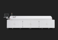
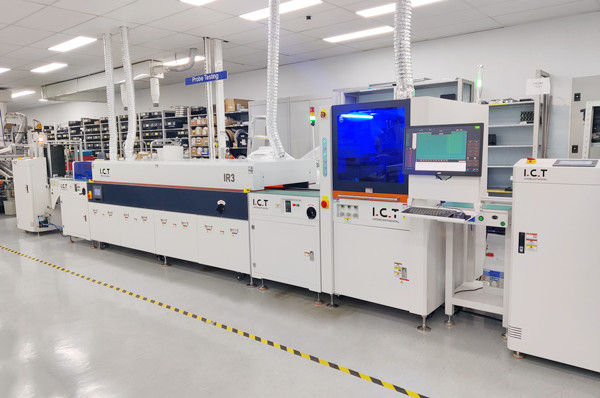
Equipment shapes which defects you fight and how wide your process window is. A reflow oven with more controlled heating zones and stable convection gives you a gentler, more uniform ramp, which supports the bridging control in Section 6 by reducing paste disturbance during heating. Cooling control matters too, because it sets how the joint freezes. For a view of how configurations are positioned by application, our overview of SMT reflow oven solutions groups them by process window and product type.
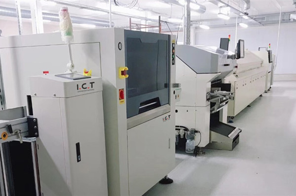
Where fine-pitch and lead-free products dominate, a machine built for zoning flexibility and consistent hot-air convection pays for itself in less profile tuning and fewer marginal joints. A typical example is the modular hot air reflow oven in the I.C.T Lyra series, which pairs a multi-zone heating chamber with a dedicated cooling stage and optional nitrogen support.
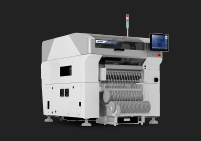
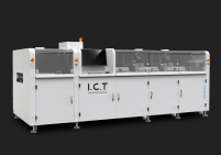
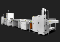
Bridging prevention is a system problem, and it is easier when the printer, stencil, placement, and oven are specified and supported as one line rather than as separate purchases. I.C.T supplies complete SMT turnkey lines, including the Lyra 622, 733, and 933 series reflow ovens with their different zone counts, plus nitrogen, vacuum, and board-support configurations for demanding products. The same process engineers who help plan the line can support installation, training, and on-site technical service.
The practical recommendation is to let your defect data drive the equipment decision. If your bridges are print and placement driven, invest in stencil and printer control first; the oven is the last lever, not the first. If your products are fine-pitch and lead-free, zoning and convection control on the oven become worth the investment.
9.1 What is the most common cause of solder bridging?
Excess solder paste is the leading cause, usually from a stencil aperture or thickness that deposits more than the pad gap can hold. Paste slump, placement pressure that squeezes deposit sideways, a too-fast ramp, and a too-small pad pitch are the other usual contributors. In practice, most bridges are print or placement defects that only become visible after reflow, so verify the deposit and stencil before changing any oven setting.
9.2 How do I know whether a bridge is caused by the profile or by printing?
Compare the bridge rate against a measured profile on the real board and against your paste-volume and placement data. If moving the ramp and peak within a reasonable range does not change the rate, the cause is almost certainly upstream in paste, stencil, or placement. If it responds reproducibly to a gentler ramp, the thermal window was part of the problem. Start with the print and placement checks because they are the more common root.
9.3 Can a bridge form even if the paste volume is correct?
Yes. A correct volume can still bridge if the paste slumps before reflow, if placement pressure squeezes it into the neighbor gap, if the part is placed off-center, or if a too-fast ramp disturbs the soft paste. Pad pitch that is too small also removes the margin that would otherwise absorb these smaller errors. Volume is the first lever, not the only one.
9.4 Does fine pitch always mean bridging?
No, but fine pitch removes the margin for error, so the same small deposit error that is harmless on a coarse part becomes a bridge on a tight one. Fine-pitch products need tighter stencil design, stricter volume control, and careful placement pressure to stay clean. With the right discipline, fine-pitch boards can be built reliably; without it, they bridge repeatedly.
9.5 Will a nitrogen atmosphere prevent bridging?
Not by itself. Nitrogen reduces oxidation and can improve wetting margin for lead-free alloys, but it does not fix an overfilled aperture, a slumping paste, or excessive placement pressure. It is a supporting control for wetting, not a bridge preventive. The real bridge controls are paste volume, stencil design, print stability, placement pressure, and a sensible ramp, in that order.
9.6 What single change most reduces bridge rate?
Documenting and trending the paste deposit volume, because volume is the root of most bridges and measuring it turns a guess into a number you can act on. Add placement-pressure qualification and a measured profile, and you have the three controls that cover the majority of cases. Without that baseline you cannot tell a real fix from a coincidence.