English
Views: 0 Author: Elsa Long Publish Time: 2026-11-04 Origin: Site


The choice between the RS, RX and LX families is not a choice between good and better machines. It is a choice between three architectures that each trade something away, and the trade only becomes visible when you write your product down in numbers. RS buys component range and board envelope with speed. RX buys placement speed with component size, height and feeder positions. LX tries to hold feeder capacity and speed at the same time, which is why it sits awkwardly between the other two in most comparison tables. Making the JUKI RS vs RX vs LX mounter decision well means knowing which of your requirements is genuinely hard and which is merely a preference. This comparison works from the figures published on the current product pages and from the operational consequences of each architecture; the machine range itself sits in the SMT placement equipment range, and every calculated example below is marked as hypothetical.
The article is organized as a decision, not a catalog. The first chapter explains what each route optimizes and why the published numbers cannot be compared directly. The next three chapters take RS, RX and LX in turn and describe the boards each one is built for, including the cases where the obvious choice is wrong. The remaining chapters reduce the comparison to three tests you can run on your own BOM, then cover the costs that decide a close call, the implementation steps that protect the decision, and the questions buyers ask most often. Where a figure is quoted, it comes from the supplier's published specification; where a number is calculated, the assumptions are written next to it.
The three families answer three different questions. RS asks how wide a component and board range one platform can cover without becoming slow. RX asks how many small chips per hour a machine can place in the smallest possible footprint. LX asks whether a wide BOM can be run at chip-shooter speed without giving up feeder positions. Once the questions are stated that way, the comparison stops being about which machine is better and becomes about which question your plant is actually asking. A plant that builds 90 percent chip boards at volume has a different question from a plant that builds control boards with connectors, shielding and a tall transformer, even if both describe themselves as high mix.
Published specification tables encourage the wrong comparison because they put all three routes in the same columns. A single number for placement speed, a single board size, a single feeder count. Those columns hide the design decisions that produced them: the head type, the number of nozzles, the vision arrangement, the component height clearance and the physical width of the feeder bank. Two machines can share a column value and behave completely differently on your board. This chapter explains what each route is optimizing, how to read the figures without being misled, and where the routes overlap enough that the decision has to be made on cost rather than capability. Throughout, the JUKI RS vs RX vs LX mounter comparison is treated as a test of fit rather than a ranking of machines.
Route | Published architecture | What the route gains | What it gives up |
|---|---|---|---|
RS | Inline head, wide component and board coverage | Large and tall components, large panels, high feeder count | Peak placement speed |
RX | Rotary head, narrow body, small-chip focus | Highest chips per hour per metre of floor | Component size and height, feeder positions |
LX | Flexible chip mounter with high feeder input | Speed and feeder capacity together | Simpler, cheaper single-route planning |
RS is built around an inline head that can carry a wide range of nozzle types and reach a large component without losing accuracy. That design pays for itself on boards where the component mix is genuinely wide: a 74 mm square connector next to 0201 chips, a 25 mm tall part that the head must clear, a panel that measures 650 × 560 mm. The cost is cycle time, because an inline head places fewer components per hour than a rotary head doing the same job. RS is therefore the route for boards where the hard requirement is coverage, not volume.
RX is built around parallel rotary heads that pick several components per revolution and place them in quick succession. That is why the published rates climb so steeply, and why the same tables show a narrow body, a smaller board envelope, a lower component height and fewer feeder positions. The design is coherent: a machine that places a hundred thousand small chips an hour does not need to carry a 74 mm connector, and the floor space saved by the narrow body is part of the value. LX takes the rotary-head speed and widens the feeder provision, which is the compromise a plant needs when its BOM is broad but its volume is high.
Three cautions apply to every number in this comparison. First, the placement speed is an optimum figure measured under favorable conditions; it is not a production rate, and the gap between optimum and realistic varies by head type. Second, the feeder count is a maximum that depends on feeder width, so a count quoted for 8 mm tape does not describe a bank loaded with 24 mm tape and a tray. Third, the component range is stated as extremes, and a machine at the extreme of its range usually needs a specific nozzle, a slower mode or both. None of this makes the published figures dishonest; it makes them a starting point rather than an answer.
The practical fix is to convert every published figure into the unit your plant manages. Speed becomes boards per shift after derating and after changeover. Feeder count becomes unique BOM lines that can stay loaded. Component range becomes the count of parts that need a special nozzle or a second process. The seven-input JUKI selection framework describes that conversion in full; for this comparison it is enough to keep the three conversions in view while reading the route chapters that follow.
The routes overlap more than the tables suggest, and the overlap is where most projects actually sit. A board with 400 placements, mostly 0402 and 0603 chips plus a dozen 12 mm connectors, can be built on any of the three. On that board, RS will be slower than RX and LX but may need no second process; RX will be fastest on the chip portion but may send the connectors elsewhere; LX may clear both without a second machine but at a higher price than either. The decision then depends on volumes, changeover frequency and the cost of a second process, not on capability.
The overlap also explains why two plants with similar products can justify different choices. A plant that runs one product for three weeks has no changeover problem and can accept a narrower feeder bank; a plant that changes products twice a day needs positions more than it needs peak speed. Write down which side of that line you are on before reading further, because it changes which chapter matters most. If your products are dominated by few, large, mixed boards, the RS chapter is your decision. If they are dominated by small-chip volume, RX is. If they are broad and high volume at once, LX is the route to examine most carefully.
RS is the route that most engineers describe when they say they need a flexible machine, and the published figures explain why. In the current tables the RS-1R is listed at 47,000 CPH optimum with a plus or minus 35 micron accuracy at Cpk of at least 1, a board envelope of 650 × 370 mm, up to 112 feeder inputs and a component height of 25 mm. The RS-1XL extends the board envelope to 650 × 560 mm at 42,000 CPH. The largest component is published as 74 mm square or 150 × 50 mm, and the smallest as 0201 metric. That combination is unusual, and it is what the route sells.
What the table does not say is what those numbers cost in practice. A machine that can place a 74 mm connector and a 25 mm tall part needs clearance, a head travel that accommodates it and a nozzle set that covers both ends of the range. Those requirements add mass to the head and time to the cycle. RS is therefore not a slow machine by any reasonable standard; it is a machine whose speed is spent on capability. If your BOM never asks for that capability, you are paying for it without using it, which is the most common way an RS purchase disappoints.
Two limits decide most RS cases, and neither is the placement speed. The first is the largest component body. If your board carries a connector, a shield frame or a through-board module larger than the RX route can handle, RS is not a preference but a requirement. The second is component height. A published clearance of 25 mm means the head can pass over a tall part already placed; a machine limited to 3 mm cannot, and the consequence is a program that must sequence tall parts last or a part that has to be placed by hand. Height limits are easy to miss because they rarely appear in the same sentence as the component range.
Check both against the actual BOM, not against the product family. Take the five largest and five tallest parts and confirm each one against the published range, then ask which nozzle each needs. A part that fits but requires a dedicated nozzle is a recurring cost and a setup step, not a free capability. If the five largest parts all sit comfortably inside the RX route as well, the RS argument weakens considerably; if two of them do not, the argument is already settled and the rest of the comparison is about configuration.
Board envelope is the second reason plants end up on a flexible route. The RS-1XL publishes 650 × 560 mm, which covers most industrial and lighting panels but not all of them. When the panel goes beyond that, the flexible route continues in adjacent platforms rather than in the RS family itself. A useful reference point is the KE-3020VA platform for panels up to 1,210 mm, which publishes a 20,900 CPH optimum, a 9,400 CPH figure under IPC characterization and package-on-package placement support.
That comparison is instructive beyond the numbers. Extending the board envelope costs speed, because a larger gantry moving over a larger area takes longer per placement. A plant that buys envelope it does not need pays twice: once in capital and once in cycle time on every board it runs. Measure the largest panel you would accept as an order, add the rails, and stop there. The right envelope is the one that covers the realistic product plan with a small margin, not the largest one in the catalog.
Before comparing routes, sort your boards into three piles on a single sheet of paper. Pile one holds boards whose largest component exceeds what a rotary-head chip shooter can carry, or whose tallest part exceeds its clearance. Pile two holds boards that fit a chip shooter's component range but need more feeder positions than its bank provides. Pile three holds boards that fit both limits and therefore can run on any route. The proportions tell you what to buy: if pile one carries most of your volume, the flexible route is mandatory; if pile three dominates, the decision is about cost and changeover, not capability.
The sort also prevents a common error, which is sizing the machine for the exception. One board with a 40 mm connector in a product family of twenty does not justify a flexible platform for the whole plant; it justifies a second process, a subcontractor or a small dedicated machine. Conversely, one high-volume board that needs 180 feeder positions does justify a large bank, even if every other board is simple. Do the sort by volume, not by part count, and the answer usually becomes obvious within the hour.
RS is the wrong route when the boards it protects are a small share of the volume and the rest of the plant is chip-dominated. In that case the flexible platform spends most of its life placing 0402 chips at a fraction of the rate a chip shooter would achieve, and the capability it carries sits idle. The honest alternative is to split the BOM: a chip-focused machine for the volume and a smaller flexible machine, or an outsourced step, for the parts that need coverage. That split is usually cheaper than one oversized flexible platform, and it gives the line a fallback during maintenance.
The second wrong-route case is a plant that expects its product mix to stay narrow but buys flexibility for a hypothetical future. Flexibility has a real annual cost in cycle time, and a future product that never arrives never repays it. If the product plan is genuinely uncertain, buy capacity and feeder positions you can use today and keep the envelope margin modest; then let the second machine handle the change when it actually comes. That sequence costs less than insuring against every possible board at the first purchase.

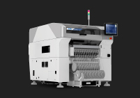
RX exists to answer one question: how many small components can be placed per hour on a given amount of floor. Every design decision in the family follows from that, and the published figures show the pattern clearly. The RX-7R is listed at 75,000 CPH optimum with parallel rotary heads, a 510 × 450 mm board, 76 feeder inputs, a component height range of 3 to 10.5 mm depending on head, components from 03015 metric up to 25 mm square, and a body width of 998 mm. The RX-8 is listed at 100,000 CPH with a P20 rotary head, 56 feeder inputs approximately, a component height of 3 mm and a largest component of about 5 mm square.
Those numbers describe a coherent machine and a narrow one. The narrow body is not a marketing detail; it is what lets a plant fit three placement platforms where two flexible machines would have stood, and that is often worth more than the headline rate. The chip-shooter logic also explains the low feeder counts: a bank of 56 positions is not a defect, it is the consequence of a machine designed to run a small number of high-usage lines at very high speed. The route pays when your BOM looks like that, and it stops paying when it does not. That boundary, more than any headline rate, is what the JUKI RS vs RX vs LX mounter choice turns on.
A rotary head carries several nozzles on a rotating turret. As the turret turns, one nozzle picks a component while another places one, so the head does not travel to a feeder and back for every placement in the way an inline head does. The saving is in travel and in the sequencing of pick and place, and it compounds when most of the components come from adjacent feeder positions with similar pick heights. That is why chip shooters publish rates that inline-head machines cannot match, and why those rates depend on a BOM dominated by small tape-fed parts.
The RX-6B model in the RX family is a useful illustration of how the route is positioned rather than a specification to memorize: the page presents it as a compact platform that handles small and large components in daily work, supports a practical feeder load and uses vision for placement verification, while keeping a narrow footprint. That framing is the honest one for a rotary-head machine. It is fast, it is compact, and its practical ceiling is set by the component mix rather than by the rate printed on the page.
Three limits come with the rotary-head design, and each one shows up as a concrete production problem. The first is component size. A published maximum of 25 mm square on the RX-7R and about 5 mm on the RX-8 means that connectors, shields and large modules cannot be placed there at all, so the BOM has to be split. The second is height. A 3 mm clearance on the RX-8 is generous for chips and restrictive for almost anything else, and it also constrains the order in which parts can be placed. The third is feeder positions, where 56 to 76 inputs is a fraction of what a flexible platform offers.
None of these limits is a fault. Together they define the machine's role. The problem only appears when a buyer treats the speed figure as a general capability and discovers the limits after the order. The table below collects the published figures for the two routes side by side so the trade is visible in one place; treat every value as a published claim to confirm against the current datasheet rather than as a measured result.
Published item | RS-1R (flexible route) | RX-7R | RX-8 |
|---|---|---|---|
Optimum placement speed | 47,000 CPH | 75,000 CPH | 100,000 CPH |
Largest component | 74 mm square or 150 × 50 mm | 25 mm square | About 5 mm square |
Maximum component height | 25 mm | 3 to 10.5 mm, head dependent | 3 mm |
Feeder inputs (maximum) | 112 | 76 | 56 approximately |
Board envelope | 650 × 370 mm | 510 × 450 mm single lane | 510 × 450 mm approximately |
Machine width | About 1,500 mm | 998 mm | 998 mm |
The calculation has two sides and both have to be real. On the gain side, estimate the time saved per board by moving the chip portion from a flexible platform to a chip shooter. On the cost side, estimate what the split adds: a second machine, a second program, an extra handling step for the boards that must move between platforms, and the changeover time that the split introduces. If the saved time multiplied by the loaded hourly cost of the line does not exceed the added cost within a reasonable payback, the split is an engineering preference rather than a business case.
A hypothetical example makes the shape clear. Suppose a board carries 260 placements, of which 240 are chips and 20 are connectors that a chip shooter cannot handle. Moving the 240 chips to a machine that runs twice as fast on chips saves roughly half of the chip cycle time, but the board still has to visit the flexible platform for 20 placements, which now consumes a full machine cycle for a small amount of work. Unless that flexible platform is also doing something else at the same time, the split can easily cost more in handling and idle time than it saves. The split pays when both machines are busy, which is a line-design question rather than a machine question.
LX addresses the case the other two routes handle awkwardly: a BOM broad enough to need a lot of feeder positions, at a volume high enough to need chip-shooter speed. The published page for the LX-8 positions it as an advanced flexible chip mounter, stating placement capability up to 100,000 components per hour under favorable conditions, component handling down to 0201 or 03015, feeder provision that reaches 112 inputs on some models, and a 998 mm body width. It does not publish a separate specification table of its own, so the honest reading is that the LX route shares architecture with the high-speed families while extending feeder capacity, and that any figure must be confirmed on the current datasheet for the exact model and build.
That caveat matters because LX is the route most likely to be oversold in conversation. The phrase flexible chip mounter invites buyers to assume RS-level component range with RX-level speed, and the published data does not support that assumption in every direction. What the route genuinely offers is more feeder positions at high placement rates in a narrow body. Whether that combination covers your component range is a separate question, answered by the same range check you would apply to any other model. The JUKI placement machine catalog is the right place to see which models sit in the family and how the published descriptions differ.
A wide BOM is not a BOM with many placements; it is a BOM with many unique lines. That distinction is the whole argument for high feeder capacity. A board with 900 placements from 40 lines is a speed problem. A board with 300 placements from 180 lines is a feeder problem, and no amount of placement speed fixes it, because the bottleneck is how many different parts can stay loaded at once. When that board also has to run at volume, the plant needs both speed and positions, which is precisely the gap between RX and RS.
Quantify the gap before you look at models. Count unique lines by tape width, apply the lane rule for the feeders you intend to buy, add the tray and stick requirement, and compare the total with the published feeder inputs. If the number lands below 56, the RX route is viable on feeder grounds. If it lands between 80 and 120, LX and RS both become candidates and the decision moves to speed and component range. If it lands above 160, you are outside all three and should be looking at multiple machines or a different configuration entirely.
The clearest way to place LX is on two axes at once: feeder positions and component coverage. RS occupies the high-coverage, high-position corner with moderate speed. RX occupies the high-speed, low-position corner with narrow coverage. LX aims at high speed with high positions, which is the corner a broad-BOM, high-volume plant needs. The unresolved question in that corner is component coverage, and the answer differs by model and build, which is why the datasheet check is not optional.
Use the position to frame the conversation with a supplier rather than to conclude it. Ask which LX build reaches the feeder count you need, what component range that build carries, what height clearance it provides, and which nozzle families it requires to cover your extremes. Those four answers, in writing, convert a route position into a configuration you can compare against an RS or RX offer. If the answers come back vague, the route may still be right, but the quotation is not yet a quotation.
The configuration decisions inside LX mirror the other routes but with a different weighting. Feeder type comes first, because the whole point of the route is positions: electronic double-lane feeders on 8 mm tape can nearly double the effective capacity of the bank, and that changes which model clears the requirement. Head and nozzle configuration comes second, since covering both ends of a wide component range may need more than one nozzle family, and each family adds a setup step and a spare-part line. Vision settings come third, because the smallest components in the BOM determine the resolution you must run, and running that resolution on every placement has a cycle-time cost.
Then decide how much of the BOM stays loaded permanently. A wide BOM usually has a stable core of high-usage lines and a long tail that changes per product. Keep the core loaded, stage the tail on carts, and size the bank so that a changeover swaps a prepared cart instead of reloading reels at the machine. This is the same discipline the RS and RX routes need, but it pays more here because the bank is the reason you chose the route in the first place. A high-position machine that is reloaded manually every shift is an expensive way to avoid a cart.

Three tests reduce the route comparison to numbers you can defend in a meeting. They are ordered by hardness: the first eliminates models outright, the second eliminates configurations, the third only ranks what survives. Running them in that order prevents the most common analytical mistake, which is comparing placement speeds between machines that cannot build the board in the first place. Each test takes an afternoon with the BOM and the published figures, and together they produce a one-page decision record that survives staff changes and supplier changes.
The tests also protect against a subtler error: treating the comparison as a single decision. In most plants the right answer is a combination, with one route carrying most of the volume and another handling the tail. The tests are designed to show where the boundary between those roles should sit, rather than to crown a single winner. When the three results are written down, the combination usually becomes obvious, and so does the configuration each machine needs. That is the practical form of the JUKI RS vs RX vs LX mounter question: not which family wins, but which combination carries your volume and which carries your tail.
Sort the BOM by largest body and by tallest part, then mark each extreme against the published limits of the candidate. Anything outside the range is a hard stop for that model, not a trade-off. Pay particular attention to the middle of the distribution: a BOM whose largest part is 30 mm square sits outside the RX-7R limit of 25 mm and outside the RX-8 limit of about 5 mm, but comfortably inside the RS-1R limit of 74 mm. A BOM with a 9 mm tall relay sits inside the RX-7R range at the higher head setting but far outside the RX-8 clearance of 3 mm.
Then check the small end, because it decides the vision and nozzle requirement rather than the model. A BOM with 0201 or 03015 chips needs the resolution and nozzle family that support them, and those requirements carry a cycle-time and spare-part cost that applies whether the machine is fast or slow. Record the result as three lists: fits, fits with conditions, and does not fit. Only the first two proceed to test two, and the conditions become line items in the configuration.
Convert unique BOM lines into feeder positions using the lane rule of the feeder type you intend to buy, then add the tray and stick requirement. Compare the total with the published inputs, and treat any shortfall as a changeover that must happen mid-shift. The RX-8 chip shooter specifications illustrate the arithmetic at the tight end: a published 56 feeder inputs approximately is generous for a chip-focused BOM of 40 lines and restrictive for a 180-line BOM, even though the machine's placement rate is the highest in the comparison.
Then price the changeover you would be forced into. Count the reels that must be swapped, multiply by the time per swap including verification, and multiply by the number of changeovers per week. That number is the real cost of a short feeder bank, and it is directly comparable between models even when their speeds differ. A machine that avoids two changeovers a week can justify a meaningful premium, while a machine that avoids none justifies none of it, regardless of what the speed table says.
Calculate the sustained rate your production plan requires: placements per board, boards per month, available minutes after planned stops, and the resulting placements per minute. Then derate the candidate's published speed before comparing. A defensible starting point is to use the IPC-9850 figure where one is published, and to apply a further production efficiency assumption for feeder indexing, vision tasks and component mix. The point of derating is not pessimism; it is to compare machines on a basis that resembles the shift they will actually run.
Where a manufacturer publishes both an optimum and an IPC-9850 figure, the ratio between them is a useful sanity check on how optimistic the peak number is. The comparison pages in this range show ratios that differ substantially between models and head types, which is exactly why comparing optimum figures across routes can mislead. Write the derated rate, the resulting margin, and the assumption behind the efficiency factor into the decision record. If the margin is thin, the route is fragile; if it is wide, the extra capacity should be justified by something other than optimism.
The table below applies the three tests to a hypothetical product: 260 placements per board, 129 unique BOM lines, a 33.5 mm square connector, an 8 mm tall relay, 0201 chips, a panel of 1,150 × 520 mm and a requirement of 25,000 boards per month on two shifts. All figures are assumptions for illustration, not quotations, and the published limits quoted in the right-hand column come from the specification pages referenced in this article.
Test | Requirement (hypothetical) | What the test eliminates |
|---|---|---|
Component range | 33.5 mm connector, 8 mm height, 0201 chips | RX-8 on size and height; RX-7R on size and height; flexible platforms that stop below 33.5 mm |
Board envelope | 1,150 × 520 mm panel | RS-1R at 650 × 370 mm; RS-1XL at 650 × 560 mm; RX platforms at 510 × 450 mm |
Feeder positions | About 78 positions plus a tray bank | RX-8 at 56 inputs approximately; RX-7R at 76 inputs, marginal |
Capacity | About 19,700 CPH sustained | Nothing outright; ranks the survivors and exposes single-machine risk |
Result | Flexible route required | A second platform handles the volume that one flexible machine cannot |
When two routes both clear the three tests, the decision moves to cost, and cost here means more than the invoice. The items that separate close calls are setup time, programming effort, nozzle families, spare-part logistics and the value of having a second platform that can keep producing during maintenance. Those items are hard to compare across quotations because they are not in the quotations. They appear as labour, as downtime and as the annual surprise of a part that takes three weeks to arrive, which is why they deserve their own chapter rather than a footnote.
The order of comparison matters as much as the items. Start with the cost that recurs weekly, which is setup and changeover, then move to the cost that recurs monthly, which is consumables and nozzles, and finish with the cost that appears once but hurts, which is a capacity shortfall or an unplanned stop. A route that looks expensive on capex can be cheaper on the first two and infinitely cheaper on the third. A route that looks cheap on capex can hide all three.
Programming cost scales with the number of routes you operate, not with the number of machines. Two platforms mean two program structures, two feeder libraries, two sets of verification steps and two training curricula. In a plant with a small engineering team, that overhead is real and is often underestimated when a split line is proposed. The counter-argument is that a single flexible platform forces every product through one program structure, which is simpler to manage but slower on every board.
Nozzle strategy is the second hidden item. A flexible route that covers 0201 to 74 mm needs several nozzle families, and each family carries a spare set, a cleaning routine and a wear profile. A chip-shooter route needs fewer families but places far more components per hour, so its nozzles wear faster in calendar terms. Neither is free. The honest comparison counts nozzle consumption per million placements rather than per machine, which is the only basis that reflects what the plant will actually spend.
Spare-part availability decides how a route behaves in year three, when a head cable or a vision board fails. Ask for the parts list with lead times for the head, the vision module and the feeder interface, and ask whether consumables remain available for the specific build. A route with a strong local parts channel is worth a premium over one with a longer lead time, because the cost of a stopped line is measured in shifts rather than in parts.
The second machine is the other form of insurance. Two platforms, even of different routes, let a plant keep producing part of the BOM during a stop, and they can be balanced against each other when volumes change. One large platform is simpler and cheaper to run until the day it stops. The value of the second machine is not a specification item, so it never appears in a comparison table; it appears in the production meeting after the first unplanned stop, which is a costly place to discover the trade.
The same board costs different amounts to build on different routes, and the difference is not proportional to the machine price. A chip-shooter route reduces the placement cost per board on chip-dominated products and adds handling cost on boards that need a second process. A flexible route removes the handling cost and raises the placement cost per board on high-volume chip work. The route that minimizes total cost therefore depends on the product mix, not on the machines.
Model it once, with three numbers per route: placement minutes per board, handling minutes per board and changeover minutes per batch. Multiply by the loaded hourly cost of the line and add the annual consumable and spare-part estimate. The result is a cost per good board that can be compared across routes and, more usefully, across product families. When the per-board difference is small, the decision should default to the route that is easier to operate and service; when it is large, the numbers make the argument for you.
The table below compares the same two hypothetical configurations over five years. Option A is one flexible platform covering the whole BOM. Option B is a split between a high-speed platform and a smaller flexible platform. Every figure is an assumption for illustration, not a quotation, and the purpose is to show which cost lines actually move the total rather than to recommend either option. Read the rows in order of recurrence: the ones that repeat every week decide the total faster than the ones that appear once.
Cost line (hypothetical) | Option A: one flexible platform | Option B: split route |
|---|---|---|
Capital and configuration, year 1 | One machine, one installation | Two machines, two installations |
Feeder and cart provision | Must cover the full BOM in one bank | Split across banks, some duplication |
Programming and training | One program structure, one curriculum | Two structures, two curricula |
Changeover labour | Higher if positions are short | Lower per product, more programs to maintain |
Handling between platforms | None | Real cost on boards that need both |
Capacity risk | Single point of failure | Partial production continues during a stop |
The route decision survives only if the line around it is designed for it. A chip shooter needs a printer that can keep pace and a buffer that absorbs its output; a flexible platform needs board support and clearance for tall parts; an LX route needs feeder carts staged within reach and a changeover routine that uses them. None of that appears in a machine specification, and all of it determines whether the rate you paid for is the rate you get. This chapter covers the three implementation steps that protect the decision: layout and balance before the order, a trial that tests your own boards, and acceptance criteria written before delivery. Framed that way, the JUKI RS vs RX vs LX mounter decision becomes an implementation plan rather than a preference.
The sequencing matters because each step can invalidate the previous one. A layout that cannot accommodate the machine's service clearance turns a good choice into a bad installation. A trial that runs the supplier's reference board tests the wrong thing. Acceptance criteria written after delivery are a negotiation rather than a test. Doing all three before the order is signed costs a few weeks and prevents the scenario where a machine that is right on paper is wrong on the floor.
Draw the line at scale with the machine envelope, the feeder cart swing, the service access and the operator position. Then compute cycle time for each station on your board: printer, inspection, placement, reflow, and any buffer. The placement section should not be the bottleneck, and if it is, the answer is either a faster route or a second platform rather than a faster head in the same footprint. A platform such as the FX-3RA, rated at 66,000 CPH under IPC-9850, is also published with up to 240 feeder inputs on 8 mm tape, which makes it a useful reference point when the board mix needs speed and positions in the same platform.
Line balance also decides how many platforms you need. If the printer cycle is 22 seconds and the placement section needs 18, one mounter is enough and the second would idle. If placement needs 34 seconds, a split or a faster machine pays immediately. Do this arithmetic with the derated rate, not the optimum, and draw the result as a bar chart of station cycle times. The tallest bar is where the money should go, and it is not always the placement section.
Run the trial on your boards, with your five most difficult components, at the accuracy your product needs, with the printer and downstream process behaving as they will in production. A demonstration on a reference board proves that the machine works; it does not prove that it works on your board. Bring the largest panel if the envelope is tight, and bring the thinnest board if support is a concern, because those two cases expose clamping and deflection problems that a rigid test board hides.
Measure during the trial rather than after: placements per minute on your mix, feeder error rate across a full bank, the time to complete one changeover with a prepared cart, and the first-article result on the fine-pitch part. Ask the operator who will actually run the machine to perform the changeover while you time it. The gap between a supplier engineer's demonstration and an operator's first attempt is the real learning curve, and it belongs in the plan rather than in the first production week.
Write the acceptance criteria before the order and attach them to it. Include placement accuracy at the corners and centre of your largest panel, a full feeder bank run with address verification, a simulated changeover with program recall, a first article measured against your inspection criteria, and delivery of the software backup, spare-parts list and training scope. Add the response-time commitment for service and the lead time for the head and vision module. These items cost nothing to specify and are difficult to obtain later.
Handover is the last chance to convert promises into records. Keep the signed acceptance sheet, the configuration list with serial numbers, the backup media and the training attendance. Photograph the installed feeder layout and the board support setup. Those records are what makes the next changeover, the next product introduction and the next service call faster than the first, and they are the difference between a machine that was installed and a machine that was integrated.
Compare the three routes against your own board
Send us the five boards, the BOM summary and the panel dimensions, and we will run the three-test filter against the RS, RX and LX routes and tell you which one clears your range, your feeder plan and your capacity target, and where a split would beat a single platform. The review states the published limits it used, marks any figure that needs confirmation on the current datasheet, and writes the efficiency assumption next to the capacity calculation so the number can be defended internally. If your mix fits one route cleanly, you will get a single recommendation with the configuration it needs; if it does not, you will get the combination and the reason, including the handling cost that a split introduces. Either way, the decision record is yours to keep and to reuse at the next product introduction, and no figure in it depends on a claim we cannot trace to a published source.
RX is the fastest route for small chips, and that is all the published figure claims. It is not the best choice if your BOM contains a connector larger than about 25 mm square, a part taller than the published clearance, or more unique lines than its feeder bank can hold. In those cases the RX route either splits the BOM across two machines or forces a manual step, and both add cost that the speed gain may not repay. The best choice is the route that clears your three tests, not the one with the highest number in the speed column.
Compare component range and feeder positions together. RS publishes the wider component coverage, including large bodies and a 25 mm height clearance, along with a high feeder count. LX publishes higher placement rates with feeder provision reaching 112 inputs on some models. If your largest parts and tallest parts sit inside the LX build you are offered, LX gives you more speed for the same bank. If they do not, RS is the route that covers them. Ask for the LX build's component range and height clearance in writing, because the family description alone does not settle it.
A flexible platform can, if its published range covers both ends and you accept the nozzle families that the extremes require. The practical questions are how many nozzle types the program needs, whether those types are available locally, and whether the height clearance allows the head to pass over parts already placed. A machine that covers the range with three nozzle families behaves very differently from one that needs six, in setup time and in spare-part cost. Test the extremes on your own board before you commit, rather than relying on the range statement alone.
It matters when floor space is the constraint that limits how many platforms you can install. A 998 mm body lets a plant fit three platforms where wider machines would allow two, and that difference often outweighs a modest rate advantage. Two narrow machines can also split a BOM by component type, which reduces cycle time on both halves. The counter-argument is that a narrow body usually comes with a smaller feeder bank and a smaller board envelope, so the space saving has to be worth the coverage you give up.
Do not compare them directly, and prefer the IPC-9850 figure when both are published because it comes from a standardized characterization method. Where only the optimum figure exists, derate it using your own experience, then apply a further production efficiency assumption for feeder indexing, vision and component mix. The ratio between the two figures, where both are available, is a good indicator of how optimistic a peak number is, and it varies enough between head types that cross-route comparisons based on optimum figures alone are unreliable.
Run the cost of both. A split reduces cycle time on the chip portion and gives the line a fallback during maintenance, but it adds a second program structure, a handling step for boards that need both machines, and additional training. A single flexible platform removes the handling and the duplicate engineering but runs every board at flexible-route speed. The split wins when both machines stay busy and the handling step is short; the single platform wins when volumes are moderate or the engineering team is small.
Confirm four things in writing: the component range and height clearance for the exact build you are buying, the feeder count with the feeder type you intend to use, the derated placement rate on a mix resembling yours, and the spare-part lead times for the head, vision module and feeder interface. Add the acceptance test you will run and the training scope. These four answers, plus the test, convert a route comparison into a specification, and they are the items most often left vague until the installation week.