English
Views: 0 Author: Vinci Zhang Publish Time: 2026-08-13 Origin: Site
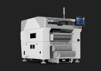
SMT machines miss, drop, or flip components when the pickup, holding, recognition, transfer, or placement process is no longer stable enough to control the component from feeder to PCB pad. These defects may look different on the board, but they often come from the same process chain: feeder presentation, nozzle condition, vacuum force, vision correction, machine parameter, and material packaging.
For an SMT production team, one missing component can stop a product from working. One dropped component can create contamination inside the machine. One upside down component placement can cause polarity error, open circuit, rework, and customer complaint. The real challenge is that these problems may appear randomly, which makes them harder to diagnose than a repeated program offset.
This guide explains the main SMT missing component causes, the most common SMT dropped component problem, and why upside down component placement happens during real production. It also shows how engineers can troubleshoot the process step by step.
Before solving the defect, engineers need to identify which type of failure is happening. Missing component, dropped component, and flipped component are related, but they are not the same problem.
A missing component means the component is not present on the PCB after placement or after reflow. The machine may have failed to pick the component, rejected it during vision inspection, dropped it before placement, or placed it in the wrong location where it was later detected as missing.
Missing component can happen before reflow or after reflow. If the part is absent before reflow, the root cause is usually pickup, feeder, vacuum, nozzle, or machine control. If it appears missing after reflow, the part may have shifted, tombstoned, blown away, or detached because of soldering process problems.
A dropped component means the machine picks the component successfully but loses it before it reaches the placement position. It may fall inside the machine, on the PCB, on the conveyor, or into another area of the equipment. This is often caused by weak vacuum, dirty nozzle, incorrect nozzle size, fast head movement, damaged component surface, or unstable pickup angle.
Dropped component is risky because it can create hidden contamination. A loose component may stay inside the machine or land on another PCB area, causing short circuit or mechanical interference.
A flipped component means the component is placed upside down, rotated incorrectly, or reversed from its required orientation. In some cases, the component flips during pickup. In other cases, it is already tilted inside the tape pocket, or the vision system recognizes the wrong side or wrong outline.
Upside down component placement is especially serious for diode, LED, IC, connector, sensor, and polarized component. Even if the solder joint looks acceptable, the function may fail.
The feeder is the first stage of component control. If the component is not presented correctly, the nozzle cannot pick it correctly. Many SMT missing component causes begin at the feeder, not at the placement head.
If the feeder pickup coordinate is wrong, the nozzle may touch the component edge instead of the center. The component may be picked at an angle, held weakly, or missed completely. The machine may report pickup error, vacuum error, or recognition failure depending on the equipment setting.
This problem often appears on one feeder lane or one component type. Engineers should check feeder calibration, pickup X/Y coordinate, pickup height, tape pitch, and component pocket center. If the problem follows the feeder after swapping feeder position, the feeder is the strongest suspect.
Feeder indexing moves the tape forward so each component reaches the pickup point. If the tape advances too much or too little, the component will not sit under the nozzle center. This can cause missed pickup, side pickup, component rotation, or dropped component after head acceleration.
Common reasons include worn sprocket, damaged tape hole, loose feeder cover, poor feeder maintenance, wrong pitch setting, or low-quality carrier tape. Engineers should not only look at the machine alarm. They should visually inspect whether the component stops in the same position every cycle.
Some component can move inside the tape pocket before pickup. This is common with small chip component, lightweight component, loose packaging, or component with smooth surface. If the component is tilted, rotated, or partially standing in the pocket, the nozzle may pick it incorrectly.
When component position inside the pocket is unstable, machine correction has limited power. Vision may reject some parts, but it cannot fix every bad pickup. The best correction is to improve material packaging, feeder stability, tape tension, and pickup parameters.
The nozzle controls the component during pickup, transfer, vision recognition, and placement. If the nozzle is not suitable or not clean, the component can be missed, dropped, or flipped.
A nozzle must match the component body. If the nozzle is too small, it may not generate enough holding force. If it is too large, it may touch the tape pocket, pick the component off-center, or pull nearby material. If the nozzle shape does not match the component surface, the component may rotate or fall during transfer.
For small chip component, LED, connector, odd-shaped component, and fine-pitch IC, nozzle selection is critical. Engineers should compare nozzle size with component dimensions and pickup surface. A correct nozzle should hold the component firmly without covering key recognition features or damaging the component body.
Nozzle contamination is one of the most common causes of random SMT dropped component problem. Dust, solder paste, flux residue, paper fiber, or component debris can block the air path or reduce sealing. A worn nozzle tip may also lose flatness and fail to hold vacuum properly.
Random missing component often points to nozzle condition. If the defect follows a nozzle number, the nozzle should be cleaned, inspected, or replaced. A preventive maintenance routine should include nozzle cleaning, nozzle height check, vacuum path cleaning, and wear inspection.
Vacuum leakage can occur at the nozzle, head seal, vacuum tube, filter, valve, or sensor. The machine may still pick some component, but the holding force is not stable enough for high-speed movement. This can cause intermittent dropped component, skewed pickup, and vision rejection.
Engineers should check vacuum value trends, not only pass/fail alarm status. A weak but not fully failed vacuum system can produce difficult random defects. Vacuum response time also matters. If vacuum builds too slowly, the head may begin moving before the component is fully secured.
Vision inspection helps the machine confirm whether the component was picked correctly before placement. But when vision data is wrong or unstable, the machine may reject good component, accept bad component, or calculate the wrong correction.
The component library should include correct body size, thickness, shape, lead position, polarity, and recognition parameter. If the library is wrong, the camera may fail to identify the component or may recognize the wrong center point.
For example, if the actual component is slightly different from the programmed package, the camera may judge it as abnormal and reject it. If the recognition window is too loose, the machine may accept a tilted or flipped component and place it incorrectly.
Camera lighting affects edge recognition, polarity mark detection, lead inspection, and component center correction. Reflective component, black body, transparent lens, shiny metal surface, and small polarity mark can all create recognition difficulty.
If lighting is too strong, the camera may lose edge detail. If lighting is too weak, the component outline may be unclear. Camera lens contamination, poor calibration, or incorrect threshold setting can also cause component camera recognition failure.
For a wider troubleshooting framework that connects pickup, feeder, nozzle, vacuum, and vision symptoms, engineers can refer to this SMT pick and place troubleshooting guide.
Upside down component placement usually means the component lost stable orientation before placement. It may flip in the feeder pocket, during pickup, during head movement, during vision centering, or at the placement moment.
If the component is not lying flat in the tape pocket, the nozzle may pick it from the side or corner. The component may rotate, stand up, or flip when vacuum is applied. This is common when the carrier tape pocket is too loose, the component is very light, or the cover tape peeling action creates vibration.
Engineers should slow down the feeder indexing speed, check cover tape tension, inspect pocket shape, and confirm component orientation inside the reel. If the issue appears only with one batch of material, packaging quality should be reviewed.
When the nozzle picks a component off-center, the holding force is not balanced. During fast head movement, the component can swing, rotate, or flip. This can happen even when vacuum strength is normal.
The correction is not only to increase vacuum. Engineers should adjust pickup coordinate, pickup height, nozzle type, and head acceleration. If a component has an uneven surface, a special nozzle may be needed to hold it from the correct point.
High production speed increases the force on the component during transfer. If the part is small, thin, tall, or irregular in shape, sudden acceleration can cause it to move on the nozzle. Once the part rotates before camera inspection, the machine may reject it or place it incorrectly if the recognition setting is too loose.
A practical test is to reduce placement speed for the affected component only. If the defect decreases, engineers can adjust acceleration, route, nozzle choice, and pickup condition before increasing speed again.
Even if pickup and transfer are successful, the component may still be lost or flipped during placement. Placement height, pressure, and air release timing must match the component and solder paste condition.
If the Z height is too high, the component may not contact the solder paste properly. It may stay attached to the nozzle and be carried away, creating a missing component. If the Z height is too low, the nozzle may press the component too deeply into paste or make it slide on the pad.
Placement height should be checked with real board thickness, PCB support condition, component thickness, and solder paste height. Board warpage can make the correct Z height different across the panel.
At placement, the machine must release vacuum at the correct moment. If vacuum release is delayed, the component may lift back up with the nozzle. If blow-off air is too strong, the component may move, rotate, or flip after release.
Release timing is especially important for small chip component and lightweight component. Engineers should review placement force, blow-off setting, nozzle dwell time, and component-specific parameter.
Solder paste should hold the component after placement. If paste tack force is weak, the component may move during conveyor transfer, nearby placement, or machine vibration. If paste is dry, contaminated, or past its usable open time, it may not hold the component well.
Process teams should control paste storage, thawing, mixing, stencil printing, open time, and board waiting time. IPC J-STD-001 is often used as a reference for soldering process and material control in electronic assembly.
Sometimes the machine is blamed for a problem caused by component design or material condition. A stable SMT process depends on both equipment setup and component manufacturability.
Some component has a curved, rough, porous, or uneven pickup surface. This makes vacuum sealing difficult. Examples include connector, shield, inductor, transformer, lens, switch, and some LED package. A standard flat nozzle may not hold these parts reliably.
In this case, the solution may be a custom nozzle, lower movement speed, adjusted pickup position, or improved packaging. Engineers should not force one nozzle type to work for all component.
Moisture-sensitive device, static attraction, and surface contamination can affect pickup and placement behavior. Very small component may stick to cover tape, feeder pocket, nozzle sidewall, or another component. This can create missed pickup, double pickup, or unexpected drop.
JEDEC J-STD-033 provides handling guidance for moisture and reflow sensitive surface mount device. Good storage, humidity control, and material preparation help reduce process variation.
Flipped or reversed component may happen when polarity mark is unclear, package orientation is inconsistent, or the vision setting does not inspect the correct feature. Some component has a very small dot, notch, bevel, or laser mark. If the mark is hard to detect, the machine may not identify incorrect orientation reliably.
Engineers should review incoming material, reel orientation, component library, camera lighting, and polarity recognition. For high-risk polarized component, the process should include AOI inspection after placement or after reflow.
Maintenance is not only about avoiding machine downtime. It directly affects component control during pickup and placement. A poorly maintained machine may still run, but it may create random defects that are expensive to trace.
If head calibration is not stable, the machine may pick or place slightly away from the intended coordinate. Nozzle changer wear can also cause wrong nozzle seating or height variation. This may lead to unstable pickup and intermittent dropped component.
Engineers should follow the machine supplier's calibration routine, including head offset, nozzle height, camera calibration, feeder base calibration, and nozzle station inspection. Calibration should also be reviewed after machine movement, head replacement, major maintenance, or collision event.
Feeders are often used heavily and may wear over time. A feeder can look normal but still advance tape inconsistently. Worn mechanical parts, dirty sprocket, weak spring, loose cover, or poor tape peeling can all cause pickup instability.
A feeder maintenance plan should include cleaning, indexing test, calibration, cover tape path check, and feeder performance tracking. If one feeder creates repeated defect, it should be removed from production until inspected.
Loose component, dust, tape scrap, cover tape fragment, and solder paste contamination can interfere with feeder movement, nozzle sealing, and board transfer. Cleanliness is especially important in high-speed placement lines.
Production teams should clean feeder area, nozzle area, conveyor, support pin, and machine table regularly. This simple discipline can reduce many random SMT dropped component problem.
A structured troubleshooting method helps engineers separate machine error from material error and process error. Without this structure, teams may keep changing program data while the real cause is a dirty nozzle or unstable feeder.
First, engineers should determine whether the problem is repeated or random. If the same component is always missing, the cause may be program setting, feeder pickup coordinate, component library, or placement height. If different component are missing randomly, the cause may be vacuum instability, nozzle wear, feeder variation, or material contamination.
Pattern tracking should include component reference designator, feeder number, nozzle number, head number, reel batch, board position, and time of occurrence.
Many teams jump directly to placement coordinate, but missing and dropped component usually begin at pickup. Engineers should observe whether the nozzle picks the component cleanly from the pocket. They should check pickup center, pickup height, vacuum value, feeder indexing, and component position inside the tape.
If pickup is unstable, placement correction will not solve the problem. The machine may only reject more component or create more random defects.
Machine logs can show pickup error, vacuum error, recognition failure, rejected component, and placement stop. AOI data can show missing component, polarity error, skew, and upside down placement. SPI data can show whether solder paste condition may be related.
By comparing these data sources, engineers can find the true stage where the failure begins. IPC notes that IPC-A-610 and J-STD-001 are often used together for assembly process control and acceptance requirements, which is useful when defining inspection standards for production teams.
Controlled testing is the fastest way to avoid false conclusions. Engineers can swap the nozzle, change feeder position, reduce speed, clean the vacuum path, adjust pickup height, or test another material reel. Only one change should be made at a time.
If the defect follows the nozzle, the nozzle is likely the cause. If it follows the feeder, the feeder is likely the cause. If it follows the material reel, packaging or component condition should be checked. This method turns a random defect into a traceable process issue.
SMT machines miss, drop, or flip components when component control becomes unstable from feeder to PCB. The most common causes include incorrect feeder pickup position, tape indexing error, component movement in the pocket, wrong nozzle, dirty nozzle, weak vacuum, poor vision data, high-speed transfer, incorrect placement height, weak solder paste tack force, and unclear polarity mark.
The best troubleshooting approach is to identify the defect pattern, observe pickup directly, compare machine data with AOI and SPI data, then change one factor at a time. Repeated missing component usually points to setup or program data. Random missing component often points to nozzle, vacuum, feeder, or material variation.
I.C.T provides professional one-stop SMT solution for electronics manufacturers, including SMT line planning, pick and place process support, feeder and nozzle optimization, reflow soldering, inspection, training, and production troubleshooting. For factories facing repeated missing, dropped, or flipped component, a full process review is often more effective than only adjusting one machine parameter.
The most common SMT missing component causes are missed pickup, weak vacuum, wrong nozzle, feeder indexing error, incorrect pickup position, unstable component inside the tape pocket, and poor placement height. If the same component is always missing, engineers should check program data, feeder coordinate, and component library. If different component are missing randomly, nozzle contamination, vacuum leakage, feeder wear, or material variation is more likely.
An SMT machine usually drops component after pickup because the holding force is not stable. This can happen when the nozzle is dirty, worn, too small, or not matched to the component surface. Vacuum leakage, blocked filter, fast head acceleration, and off-center pickup can also cause dropped component. Engineers should check whether the problem follows a nozzle number, feeder number, or material reel to isolate the source.
Upside down component placement is often caused by unstable component orientation before or during pickup. The component may be tilted in the tape pocket, picked off-center, rotated during head movement, or accepted by an incorrect vision setting. It may also happen when polarity marks are unclear or reel orientation is wrong. Engineers should check packaging, pickup point, nozzle match, vision library, polarity recognition, and AOI inspection rule.
Yes, solder paste can contribute to missing or flipped component, especially after placement. If paste tack force is weak, the component may not stay in place before reflow. If paste volume is uneven, the component may move, tilt, or tombstone during reflow. Engineers should compare pre-reflow and post-reflow inspection. If the component is present before reflow but missing or displaced after reflow, paste printing and reflow process should be checked.
Factories can reduce these defects by controlling the full placement chain. This includes feeder calibration, nozzle cleaning, vacuum inspection, correct nozzle selection, pickup coordinate verification, vision library review, placement height optimization, material packaging inspection, and AOI feedback. The team should record defect by component, feeder, nozzle, head, and reel batch. This makes the root cause easier to find and prevents the same issue from returning.
Missing, dropped, and flipped component are not isolated machine alarms. They are signs that the SMT placement process has lost stable control over the component. The root cause may come from feeder presentation, nozzle condition, vacuum force, camera recognition, material packaging, placement parameter, or solder paste behavior.
When engineers troubleshoot the process step by step, the defect becomes easier to solve. A stable SMT line does not depend on one good machine setting. It depends on consistent material handling, accurate pickup, reliable vacuum, correct vision recognition, and disciplined maintenance. For manufacturers that need practical support, I.C.T can help review the SMT process and build a more reliable one-stop production solution.