English
Views: 0 Author: Vinci Zhang Publish Time: 2026-08-05 Origin: Site
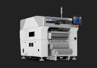
Reducing SMT component rejection and material waste starts with controlling the real pickup process, not simply lowering machine alarm sensitivity. In a modern SMT line, rejected components, empty pickups, dropped parts, vision rejects, and repeated feeder alarms can create direct material loss and hidden production costs. These issues are closely related to SMT pick and place machine performance, including feeder accuracy, nozzle condition, vacuum stability, component recognition, and process control capability.
A practical improvement plan must connect machine data with feeder presentation, nozzle maintenance, vacuum monitoring, component packaging, vision recognition, and operator practices. By optimizing both equipment conditions and process management, manufacturers can improve pickup success rates and maintain stable placement quality.
This guide explains how manufacturers can reduce SMT component rejection, minimize material waste, and improve SMT pickup success rate through a structured engineering approach. It is written for SMT process engineers, production managers, technicians, and factory owners who need lower waste without sacrificing placement quality. For manufacturers looking to improve placement stability from the equipment level, selecting a reliable SMT pick and place solution is also an important foundation.1. Build a Clear Rejection and Waste Baseline
A factory cannot reduce what it does not measure clearly. Many SMT teams know that the machine is "throwing too much material", but they do not always know which part number, feeder, nozzle, head, shift, or material lot creates the waste. The first step is to build a rejection baseline that separates normal process variation from abnormal loss.
Total rejected component count is useful, but it is not enough. A better report should show rejection by component type, feeder slot, nozzle ID, head number, machine lane, product model, material lot, and production time. This makes the rejection pattern visible. If one feeder creates most of the loss, the solution is different from a case where one component fails across several feeders.
For example, repeated rejection on one small resistor may point to tape pocket variation, feeder pitch, static charge, or nozzle size. Rejection across many component on one nozzle may point to contamination, wear, or vacuum leakage. Rejection after one shift change may point to loading method, feeder maintenance, or operator training.
Not every rejection is bad. A placement machine should reject component that are mis-picked, damaged, rotated outside tolerance, or not recognised correctly. The target is not zero rejection at any cost. The target is fewer false rejects, fewer avoidable pickup failures, and fewer repeated material-loss patterns.
When a team widens vision tolerance only to reduce alarms, it may reduce visible waste but increase hidden quality risk. The right approach is to keep the machine's quality protection while improving the physical and data conditions that cause good component to be rejected.
Feeder presentation is one of the strongest drivers of SMT component rejection. The nozzle can only pick what the feeder presents. If the component arrives off-centre, tilted, lifted by cover tape, or trapped in the pocket, the pickup process becomes unstable before the machine head even moves.
Feeder indexing must match the component tape pitch. A small indexing error can make the nozzle pick near the edge of a component instead of the centre. This increases missed pickup, tilted pickup, nozzle contact with the tape pocket, and later vision rejection.
Engineers should check feeder calibration, tape guide condition, pitch setting, reel tension, and pickup coordinate. The most useful inspection is often visual: run the feeder slowly and watch whether the component stops in the same stable location every time. If the presentation point moves between cycles, software correction will not solve the root cause.
Cover tape can disturb component position during peeling. If the peel angle, peel force, or tape path is unstable, small component may jump, rotate, or sit higher in the pocket. Splice areas can also create short periods of abnormal rejection. A good material-waste reduction plan should include cover tape checks, splice inspection, and reel-change discipline.
Operators should not treat a splice as a minor detail. A poor splice can create machine stop, missing pickup, and material loss. A simple checklist for reel loading, cover tape routing, and splice inspection can reduce repeated waste without changing the placement program.
To improve SMT pickup success rate, factories must treat the nozzle and vacuum system as process-critical tools. A nozzle may look simple, but its size, surface, cleanliness, wear, and seal quality strongly affect whether a component can be picked, held, recognised, and placed correctly.
The nozzle must match the component's body size, surface, weight, pickup area, and centre of gravity. A nozzle that is too small may not hold the component securely during acceleration. A nozzle that is too large may touch leads, neighbouring tape edges, or package features that should not be contacted.
Odd-shaped component deserve special attention. For connector, shield, diode, inductor, or irregular package, the pickup point may need adjustment. The team should confirm that the nozzle touches a stable flat area and does not create a tilted lift.
Nozzle contamination is one of the easiest causes to miss because it may create intermittent errors. Dust, adhesive particles, solder paste residue, or tape debris can reduce vacuum seal. The machine may run well for a while, then suddenly reject more component when contamination builds up.
A practical maintenance plan should include nozzle cleaning, magnified inspection, blocked-hole checks, wear inspection, and replacement rules. Rejection reports should be compared by nozzle ID. If a problem follows one nozzle across different component, that nozzle should be cleaned, replaced, or recalibrated.
Vacuum data should be used before it becomes an alarm. A falling vacuum value may indicate a blocked filter, leaking hose, damaged nozzle tip, wrong pickup height, poor component surface, or feeder presentation issue. Recording normal vacuum range for common package helps engineers find drift early.
When rejection increases, the team should compare current vacuum values with the normal baseline. This is a faster path than adjusting many settings at once.
Vision recognition is often blamed when a machine rejects component. In reality, the camera may be doing its job correctly. The problem may be poor pickup, wrong library data, weak contrast, package variation, or incorrect polarity definition. Vision optimization should improve recognition accuracy while keeping quality risk under control.
Before changing tolerance, engineers should inspect the real camera image. Is the edge clear? Is the polarity mark visible? Is the component tilted? Is the lighting mode suitable for the package surface? Reflective metal, black body, transparent package, and small mark can all reduce recognition stability.
If the image itself is poor, the solution may be lighting, lens cleaning, camera calibration, or better component presentation. If the image is clear but the machine rejects good component, package library data and tolerance may need review.
Package data must match the real component. Body size, lead count, lead pitch, component height, polarity mark, pickup centre, and recognition shape all matter. A copied library may be close enough for one product but not stable for another. Library mistakes can increase both rejection and placement defect.
For quality consistency, teams can use electronics assembly references such as IPC J-STD-001J and IPC-A-610J, which IPC describes as covering assembly process controls, materials, and post-assembly acceptance criteria. These standards do not replace machine setup rules, but they support consistent quality language across the factory.
Material waste is not only created inside the placement machine. It can begin with storage, reel handling, splice quality, moisture exposure, ESD control, and package variation. A good waste-reduction plan follows the component from warehouse to feeder.
Moisture-sensitive component require controlled storage and floor-life management. Poor handling may create later reflow defects and can also affect package stability. JEDEC's J-STD-033 is a key industry reference for handling moisture/reflow sensitive devices.
Factories should verify dry storage, humidity indicator cards, floor-life records, resealing discipline, and bake rules where applicable. Even when moisture does not directly cause pickup rejection, it can contribute to broader production loss.
Small component can be affected by static charge, rough handling, or contamination. Static can make parts cling to tape, nozzle, or pocket surfaces. Handling damage may bend leads or change how the component sits in the tape. The ESD Association's ANSI/ESD S20.20 framework is a useful reference for building an ESD control programme around sensitive electronic devices.
When rejection rises after a lot change, do not assume the machine suddenly became unstable. Compare the old and new lot under the same feeder, nozzle, and camera condition. Differences in body colour, tape pocket fit, surface texture, lead shape, or polarity mark can all affect pickup and recognition.
The best factories do not only react to alarms. They turn rejection data into a continuous improvement system. This is especially important for high-mix production, frequent changeover, and expensive component.
A practical loop is simple: measure the rejection pattern, isolate the source, correct the root cause, verify the result, and update the standard work. This loop prevents the same defect from returning. It also helps new operators understand why a setup rule exists.
Measure rejection by component, feeder, nozzle, head, product, and lot.
Isolate whether the problem follows material, feeder, nozzle, camera, or program data.
Correct the physical or data root cause.
Verify the change with controlled production evidence.
Update maintenance, setup, and operator training records.
Reducing waste should not weaken quality control. A strong SMT line rejects truly bad pickup while reducing avoidable false rejection. That balance comes from better feeder setup, nozzle maintenance, vacuum monitoring, vision data, material handling, and disciplined changeover.
I.C.T supports electronics manufacturers with one-stop SMT solutions, including line planning, equipment supply, installation, training, process support, and after-sales service. For manufacturers looking at the wider troubleshooting path, this article connects naturally with the broader SMT pick and place troubleshooting framework.
To reduce SMT component rejection, first measure where and why rejection happens.
Feeder indexing, tape pocket stability, and cover tape control are major waste drivers.
Nozzle condition, nozzle selection, pickup height, and vacuum stability directly affect pickup success.
Vision tolerance should not be loosened before image quality and package library data are verified.
Material storage, ESD control, splice quality, and lot variation influence rejection and waste.
The best way to reduce SMT material waste is to turn rejection data into a repeatable improvement loop.
When a factory treats rejection data as engineering evidence, material waste becomes easier to control. The result is not only lower cost, but a more stable SMT process, stronger operator confidence, and better delivery reliability for customers.
The fastest reliable way is to identify the largest repeated rejection pattern. Instead of adjusting all settings, engineers should find whether the issue follows one component, one feeder, one nozzle, one material lot, or one program. If one feeder creates most of the rejects, feeder indexing and tape presentation should be checked first. If one nozzle is involved across several component, nozzle condition and vacuum should be checked. This targeted method is faster than random parameter changes.
The factory should reduce false rejection and avoidable pickup failure while keeping real quality protection active. This means improving physical pickup conditions, feeder setup, nozzle maintenance, material handling, and library accuracy. The team should avoid simply widening vision tolerance to make alarms disappear. A lower alarm count is not useful if poor placement or wrong orientation passes into production.
A reel change can introduce new tape tension, splice condition, pocket variation, cover tape behavior, or material lot difference. Even if the part number is the same, the component may sit differently in the pocket or have slightly different surface appearance. Operators should inspect the new reel, splice area, cover tape path, feeder loading, and first pickup result after changeover.
Both are important because they control different parts of the pickup chain. The feeder presents the component, and the nozzle picks and holds it. A perfect nozzle cannot pick a component that is shifted in the tape pocket. A perfect feeder cannot prevent rejection if the nozzle is worn, dirty, or leaking. The best approach is to track rejection data and maintain both feeder and nozzle based on actual risk.
Professional support is useful when rejection remains high after normal feeder, nozzle, vacuum, vision, and material checks. It is also valuable during new line setup, new product introduction, high-mix production, or when expensive component create large waste cost. A full-line SMT solution provider can review equipment matching, setup standards, maintenance routines, operator training, and process control together instead of treating each alarm separately.