English
 Views: 0 Author: Vinci Zhang Publish Time: 2026-08-25 Origin: Site


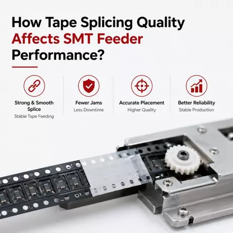
Tape splicing quality has a direct effect on SMT feeder performance because the feeder must pull the connected tape smoothly, consistently, and without interruption. If the splice is misaligned, too thick, too weak, or contaminated, the feeder may jam, lose stability, or cause placement interruption. In many SMT lines, the real problem is not simply that a reel runs out. The deeper issue is whether the splice can pass through the feeder cleanly and continue supplying components with the same reliability as an unspliced reel.
Understanding how tape splice affects feeder performance helps factories reduce hidden downtime, prevent recurring feeder alarms, and improve overall line stability. A weak or inconsistent joint may not fail immediately at the splicing station, but it can still create a later SMT feeder splice joint problem when the tape begins moving through the feeder path.
This article explains why splice quality matters, which splice defects most often affect feeders, how to diagnose feeding problems, and how to improve component tape feeding reliability in real production.
Table of Contents
An SMT feeder is designed to advance carrier tape in small, controlled steps so the placement machine can pick components at the correct position. That means the feeder expects the tape to stay flat, evenly guided, and mechanically stable. Any change in tape thickness, edge shape, alignment, or surface condition can affect how the feeder moves the material.
When the splice is well made, the feeder should barely notice the transition between reels. When the splice is poor, the feeder may suddenly meet extra resistance, lose step accuracy, or stop altogether. This is why splice quality is not a minor detail. It is part of the feeder's operating condition.
The feeder moves tape through a narrow mechanical path. If the joint is too thick or uneven, the tape may not move with the same resistance as the rest of the reel. If the joint is misaligned, the tape may shift sideways or catch inside the guide.
Feeder stability depends on predictability. The more consistent the tape shape and splice geometry are, the more stable the feeder motion will be. In practical terms, that means a good splice helps protect both component supply and placement continuity.
The feeder does not operate in isolation. It supports the pick and place machine by presenting each component at the correct location for pickup. If the tape is advanced unevenly because of a bad splice, the placement head may pick from the wrong pocket or miss the component entirely.
That is why splice quality affects more than just the feeder. It also affects the downstream machine. A reliable splice supports stable component presentation, which helps the placement system keep its cycle rhythm.
Some splice defects cause immediate jams. Others create slow, repeated issues that are harder to notice at first. The feeder may still run, but with more alarms, more hesitation, or more operator attention.
These hidden interruptions are often more costly than obvious stops because they accumulate across many reels and shifts. A factory can lose significant time if the same small splice issue repeats throughout the week.

There are several ways a splice can affect feeder behavior. The most common are thickness variation, misalignment, weak joint strength, edge damage, and contamination. Each one affects the tape path differently, but all of them reduce feeding reliability.
Before changing the feeder or blaming the placement machine, it is worth checking whether the splice itself introduced the problem. Many line stoppages begin at the tape joint rather than inside the feeder.
A splice that is too thick may not pass smoothly through the feeder path. Even a small increase in thickness can create resistance if the feeder tolerance is tight or the tape path is narrow.
Uneven joints are also a problem because the tape may lift slightly as it moves forward. That can cause a short pause, an alarm, or a small misfeed that becomes visible only during operation.
If the old and new tapes are not aligned on the same centerline, the feeder may receive side pressure as the splice passes through. This side load can increase wear, create movement irregularity, or trigger feeding instability.
Misalignment is one of the easiest problems to prevent and one of the most damaging when it is ignored. A splice can look acceptable at the workbench and still behave poorly in the feeder.
Some joints hold during manual inspection but fail once the feeder begins pulling the tape repeatedly. A weak joint may open, lift, or split during movement, causing a sudden stoppage.
When this happens, the issue is often recorded as a feeder failure, but the real root cause is splice strength. This is why factories should treat splice joint quality as part of feeder reliability, not only as a material preparation task.
For a broader explanation of the machine and joining process, see this guide on SMT reel splicing operation basics.
SMT feeder splice joint problems usually appear when the joint shape, strength, or orientation is not compatible with the feeder design. The feeder may react with resistance, skipping, jamming, or irregular tape motion.
Although the symptoms may look similar, the cause can be quite different. That is why troubleshooting should start with the joint itself, then move to the feeder and the material path.
A jam at the splice point usually means the joint is too bulky, too uneven, or too stiff for the feeder path. It can also happen when the splice extends beyond the intended tape width or the joining material is not applied correctly.
In this situation, the tape may stop immediately after entering the feeder or may move only part of the way before the alarm appears. Repeated jams at the same point are a strong sign that the splice geometry needs attention.
Sometimes the feeder does not stop completely. Instead, it advances unevenly or loses one step near the splice. This can be harder to detect because the line may continue running for a short time.
Intermittent feeding is dangerous because it can create placement errors without obvious alarm conditions. If a splice does not advance with the same smoothness as the base tape, the feeder may not present the component pocket at the correct position.
A joint may pass through the feeder at first and fail later after repeated pulling. This is often a sign that the splice is weak, the overlap is insufficient, or the joining material was not compatible with the carrier tape.
Delayed separation is especially difficult to manage because the splice initially appears acceptable. Factories should therefore test joint stability under actual feeder movement rather than only visual inspection.

Feeder performance changes after a poor splice because the feeder's motion depends on smooth tape transport. If the splice adds resistance or instability, the feeder may need extra force to move the tape. That extra force can create inconsistency, wear, or alarm conditions.
Once the tape path becomes unstable, the feeder may also influence the pickup rhythm of the placement machine. In other words, a splice problem can spread from material handling into machine timing.
Not every feeder responds in the same way. Some feeders may tolerate small variation, while others are more sensitive to joint shape or tape stiffness. This is why a splice that works on one machine line may create trouble on another.
Factories should not assume that a tape joint is universally acceptable just because it passed one test. The actual feeder model and tape path matter.
At higher line speeds, the feeder has less time to adapt to tape irregularities. A splice that would pass unnoticed in a slower process may cause a fault in a high-speed line.
This is one reason high-volume factories often move toward more controlled splicing methods. A stable joint becomes more important as production speed rises.
Even a small splice issue becomes more serious when it happens many times a day. If a line changes reels repeatedly, the total number of opportunities for feeder disruption increases.
That is why improving splice quality can have a much bigger effect than its size suggests. The benefit compounds across every reel change.
A good diagnosis process starts by separating splice problems from feeder problems. The same symptoms can appear in both cases, so the first task is to identify whether the issue follows the splice or stays with the feeder.
When troubleshooting, the goal is to find the root cause quickly without replacing parts unnecessarily or disturbing stable production more than needed.
If the feeder runs fine until the splice enters the path, the joint is the first place to inspect. Look for thickness variation, edge lifting, misalignment, or visible damage.
If the feeder also jams with known-good unspliced tape, then the feeder itself may be contributing to the issue. That is why a controlled comparison is so useful.
Before blaming the feeder, inspect both tape ends carefully. Make sure the tape was cut cleanly, aligned correctly, and joined with suitable material. Check whether the tape edges are straight and whether the overlap is consistent.
Also verify whether the component pocket position is still correct after joining. A tape can look secure but still present the wrong feed geometry.
If possible, test the same tape and splice on another feeder of the same type. If the issue disappears, the original feeder may have a condition problem. If the issue stays with the splice, the joint is likely the source.
This comparison is one of the simplest ways to separate a SMT feeder splice joint problem from a feeder maintenance problem.
For a related view of downtime impact, see this article on how splicing supports continuous line uptime.

Improving component tape feeding reliability requires more than using a better feeder. The splice process, the machine setup, the operator method, and the maintenance routine all matter.
The strongest results usually come from standardizing the entire reel changeover process rather than trying to fix one symptom at a time.
The tape ends should be clean, flat, and free from debris before joining. Any dust, adhesive residue, or damaged edge can weaken the joint or change its thickness.
Operators should prepare the tape carefully rather than rushing to complete the splice. A few extra seconds at the preparation stage can prevent a later feeder stop.
The joint should stay as flat as possible and should be aligned with the feeder centerline. A centered and flat splice passes through the path more predictably than a raised or skewed one.
In practice, this means paying attention to both the visual joint and the mechanical path it must travel through. A good-looking splice is not enough if it does not feed smoothly.
Wrong tape direction and inconsistent joining methods are common sources of feeder instability. The factory should define one approved direction check and one approved joining method for each tape type or machine family.
This reduces operator variation and makes it easier to troubleshoot when a problem occurs. If the process is consistent, the failure pattern becomes easier to identify.
For factories with frequent reel changes or strict uptime targets, automation can improve repeatability. An automatic splicing machine helps control tape positioning and joint formation more consistently than manual handling.
When choosing equipment, some teams evaluate the intelligent SMT tape joining system as part of a broader production reliability plan.
Even a perfect splice can fail if the feeder path is dirty, worn, or misadjusted. Feeder maintenance is therefore part of the same reliability picture.
The cleaner and more stable the feeder, the more tolerant it will be of normal production variation. That makes the whole line easier to manage.
Dust, adhesive, and worn guide surfaces can make splice-related problems worse. A feeder with residue or damage may turn a borderline splice into a jam.
Regular cleaning and inspection help keep the tape path predictable. This is especially important on lines that run long shifts or high component volumes.
If the same feeder keeps showing splice-related issues while others do not, the feeder condition should be investigated. The problem may be inside the tape path rather than in the splice method.
Recording which feeder fails, when it fails, and with which tape type helps distinguish between process issues and equipment wear.
Running a known-good splice through the feeder can quickly show whether the feeder is performing normally. If the known-good tape still jams, the feeder likely needs attention.
This simple test prevents unnecessary changes to the splicing process when the feeder is actually the part that needs correction.

Some factories can resolve splice issues with better training or clearer work instructions. Others need a more advanced splicing solution because manual variation is too high or the line is too sensitive to changeover errors.
The right time to upgrade is when the same problems keep returning even after the basics have been corrected.
If the same factory repeatedly changes reels during every shift, manual variation becomes harder to control. A more consistent process may be needed to protect feeder stability.
When feeder stops are expensive, the cost of better splicing equipment is easier to justify. The goal is to reduce repeated losses, not only to make the splice station more convenient.
If splice quality changes from one operator to another, the process is too dependent on manual skill. Automation can help normalize the result and reduce feeder-related variation.
For selection context, the article on how to choose a suitable SMT splicing machine is a useful reference for production teams comparing options.
Tape splice quality has a direct effect on SMT feeder performance because the feeder depends on smooth, flat, and stable tape movement. A splice that is too thick, weak, misaligned, or contaminated can create jams, step loss, or feeding instability. In severe cases, it can stop the feeder and interrupt the placement process.
To improve reliability, factories should standardize tape preparation, confirm tape direction, keep the splice flat and centered, inspect feeder condition, and test the joint under real production conditions. When the process remains inconsistent, automatic splicing equipment can improve repeatability and reduce operator variation.
The real goal is not just to connect two reels. The real goal is to maintain component tape feeding reliability across the entire line so the feeder, placement machine, and production schedule can all stay stable. For the broader context of material changeover, see the SMT splicing machine and material changeover guide.
Tape splicing affects feeder performance by changing how smoothly the carrier tape moves through the feeder path. If the splice is misaligned, too thick, weak, or dirty, it can create resistance, jams, or unstable feeding. A good splice should move through the feeder with minimal difference from the rest of the tape.
An SMT feeder splice joint problem is usually caused by misalignment, weak joining strength, excess splice thickness, tape damage, or contamination on the tape surface. Feeder condition can also make the problem worse. The best troubleshooting method is to inspect the joint, test the same splice in another feeder, and compare results with a known-good tape.
A splice may feed normally at first and fail later if the joint is weak or only slightly too thick for the feeder path. The tape may hold during the first few movements and then separate or jam under repeated pulling. This is why splice validation should include actual feeder movement, not only visual inspection at the splicing station.
Component tape feeding reliability improves when the splice is clean, flat, centered, and made with a consistent method. Factories should also check tape direction, maintain feeders, standardize operator work instructions, and test the splice through the actual feeder. Automation can help when manual variation is still too high.
You should consider automatic splicing equipment when reel changes are frequent, feeder-related stoppages are costly, or splice quality varies too much between operators. Automatic equipment improves repeatability and can help reduce the hidden downtime caused by poor splicing. It is especially useful in high-volume or multi-shift SMT production.