English
Views: 0 Author: Site Editor Publish Time: 2024-09-29 Origin: Site


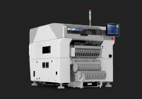
In modern PCB assembly, an SMT pick and place machine is one of the most important machines on the production floor. It takes surface mount components from feeders, aligns them through a vision system, and places them onto printed circuit boards with speed and accuracy that manual assembly cannot match.
But a pick and place machine is not just a “component placing robot.” It works as part of a complete SMT line, connecting solder paste printing, inspection, reflow soldering, and final quality control into one continuous production process. Understanding how this machine works is the first step to building a stable, efficient, and scalable PCB assembly line.
At first glance, a pick and place machine may look like a machine that simply picks up components and places them on a PCB. In real production, it does much more than that.
It must recognize PCB positions, read fiducial marks, pick components from feeders, correct component angles, and place each part accurately according to the program. These actions happen repeatedly at high speed, often thousands of times in one production run.
This is why the machine plays such a central role in SMT assembly. It combines mechanical movement, vision alignment, software control, and component feeding into one coordinated process.
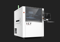
The pick and place machine works after solder paste printing and before reflow soldering. First, the solder paste printer applies solder paste to the PCB pads. Then the pick and place machine mounts components onto those printed areas.
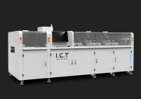
After placement, the PCB moves into the reflow oven, where the solder paste melts and forms reliable solder joints. If the components are not placed correctly before reflow, the final soldering quality can be affected.
For this reason, the pick and place process must work closely with the solder paste printer, SPI, reflow oven, and AOI system to support stable PCB assembly quality.
For factories moving from manual assembly to automated SMT production, the pick and place machine is often the real turning point. It reduces manual handling, improves repeatability, and helps the factory produce more boards with fewer placement variations.
This is especially important as electronic products become smaller, PCB layouts become denser, and delivery requirements become tighter. Whether the factory produces LED boards, industrial control boards, automotive electronics, consumer electronics, or EMS orders, stable component placement is a basic requirement for reliable production.
An SMT pick and place machine is an automated machine used to place surface mount components onto printed circuit boards during SMT assembly. It picks components from feeders, trays, or tubes, checks their position through a vision system, and places them onto the correct pads on the PCB.
The term SMT stands for Surface Mount Technology. In this process, electronic components are mounted directly onto the surface of a PCB instead of being inserted through holes. These components are usually called SMD components, which means Surface Mount Devices.
In simple terms, an SMT pick and place machine is the equipment that performs the automatic component placement step in PCB assembly.
In a standard SMT production line, the PCB first goes through solder paste printing. The printer applies solder paste to the pads where components will be mounted. After that, the pick and place machine places the required components onto those solder paste areas.
Once placement is finished, the PCB enters the reflow oven. The solder paste melts, cools, and forms solder joints between the components and the PCB pads.
This means the pick and place machine is responsible for one of the most critical steps before soldering. It does not create the solder joint by itself, but it determines whether each component is positioned correctly before the soldering process begins.
During production, the machine performs several actions in a very short time. It moves the PCB into position, reads reference marks on the board, picks components from feeders, checks the component position, corrects small angle or offset errors, and places the component onto the PCB.
These actions repeat continuously during production. The goal is not only to place components quickly, but to place them consistently and accurately.
To achieve this, a pick and place machine works together with several systems, including the feeder system, placement head, nozzles, vision cameras, motion control system, conveyor system, and software control platform.
Manual placement depends heavily on operator skill, visual judgment, and production speed. It may work for simple prototypes or very small batches, but it is difficult to maintain consistency when the PCB has many components or fine-pitch packages.
An SMT pick and place machine uses programmed coordinates and vision correction to repeat the same placement process with much higher stability. Depending on the machine configuration, it can place small chip components, ICs, LEDs, connectors, and other surface mount parts.
This is why automatic placement is widely used in modern PCB assembly. It improves production efficiency and helps reduce placement-related errors caused by manual handling.
The name “pick and place” sounds simple, but it describes one of the most important actions in SMT assembly. The machine first picks up a component from a feeder, tray, or tube, then places it onto the exact position on the PCB according to the production program.
In real production, this process is much more advanced than the name suggests. Every placement action involves component feeding, vacuum pickup, camera inspection, angle correction, PCB positioning, and precise motion control. That is why the machine is not only fast, but also highly coordinated.
The “pick” step means the machine uses a nozzle to pick up a component from the feeding system. Most SMD components are supplied in tape feeders, while larger ICs, connectors, or special components may come from trays or tubes.
During pickup, the nozzle uses vacuum suction to hold the component. If the vacuum is unstable, the component may shift, drop, or be picked incorrectly. This is why feeder condition, nozzle selection, and vacuum control all matter in a real SMT production environment.
A stable pick process is the first step toward accurate placement. If the machine cannot pick the component correctly, the following vision alignment and placement steps will also be affected.
The “place” step means the machine moves the component to the programmed position and mounts it onto the solder paste printed on the PCB pads. Before placement, the vision system checks the component’s position and angle, then the machine corrects any small offset automatically.
This step must be accurate and repeatable. A small shift may not look serious before reflow, but after soldering it can lead to defects such as component offset, poor solder joints, or polarity problems.
For high-density PCB assembly, stable placement is not just about speed. It is about making sure every component lands where it should, again and again, across the full production run.
Although “pick and place” sounds like a basic movement, the machine behind it combines many technologies. It includes precision mechanics, machine vision, motion control, vacuum systems, feeder management, and placement software.
This is why two machines with similar appearance may perform very differently in real production. The difference often comes from how well these systems work together under continuous operating conditions.
For manufacturers, understanding this point is important. A pick and place machine should not be judged only by how fast it moves, but by how consistently it can pick, correct, and place components throughout daily production.

An SMT pick and place machine is used in the middle of the SMT production line. It comes after solder paste printing and before reflow soldering. This position makes it a critical link between preparing the PCB and forming the final solder joints.
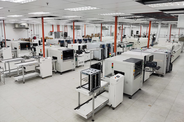
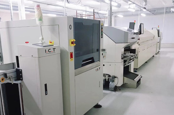
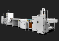
A typical SMT line may include a PCB loader, solder paste printer, SPI, pick and place machine, reflow oven, AOI, and PCB unloader. Each machine has its own job, but the placement machine is where the PCB starts to become a functional electronic assembly.
Before the pick and place process, the PCB only has solder paste printed on its pads. After the pick and place machine completes its job, the board is populated with the required SMD components.
This step changes the PCB from a prepared board into an assembled board ready for soldering. It is one of the most visible changes in the SMT process, and it also has a direct impact on the quality of the final PCBA.
If components are placed accurately, the reflow process has a better foundation for forming reliable solder joints. If placement is unstable, the following process may expose issues such as shifting, bridging, tombstoning, or missing components.
The pick and place machine does not work alone. It depends on the solder paste printer to provide a clean and accurate paste deposit. If the solder paste is misaligned or insufficient, placement quality can still be affected even when the machine places components correctly.
SPI is often used before placement to inspect solder paste height, area, volume, and offset. After placement, the PCB enters the reflow oven, where the solder paste melts and creates the solder joints. AOI is then used to inspect defects such as missing parts, wrong components, offset, polarity errors, and soldering issues.
This is why SMT quality should be viewed as a full-line process, not the result of one machine alone. The pick and place machine is critical, but it must work together with the entire SMT line.
Because the pick and place machine sits between printing and reflow, any instability at this step can affect the final output. A small placement problem may become a bigger quality issue after soldering.
At the same time, this machine also influences production rhythm. If placement is too slow, it may become the bottleneck of the line. If it is unstable, the line may stop often for adjustment, inspection, or rework.
That is why many manufacturers treat the pick and place machine as the production engine of the SMT line. It not only places components, but also helps determine how smoothly the entire line can run.
An SMT pick and place machine works through a highly coordinated process. It does not simply move parts from one place to another. It first confirms the PCB position, picks the correct component, checks the component alignment, and then places it onto the programmed location with controlled speed and accuracy.
This process happens continuously during production. For one PCB, the machine may repeat the same basic movement hundreds or even thousands of times, depending on the number of components on the board. The real value of the machine is not only speed, but its ability to repeat these actions with stable accuracy throughout the entire production run.

Before placement begins, the PCB must be positioned correctly inside the machine. The conveyor transfers the PCB into the placement area, and the machine fixes the board in place to prevent movement during operation.
Then the vision system reads fiducial marks on the PCB. These marks act as reference points, helping the machine confirm the real position and angle of the board. Even if the PCB has a small shift during transfer, the system can calculate the offset and adjust the placement coordinates.
This step is especially important for fine-pitch ICs, dense PCB layouts, and products that require tight placement tolerance. Without accurate PCB alignment, even a good placement head cannot guarantee stable results.
After the PCB position is confirmed, the machine picks components from feeders, trays, or tubes. The nozzle uses vacuum suction to lift each component from its supply position.
Once the component is picked, the vision system checks its position, angle, and sometimes its shape or polarity. If the component is slightly rotated or off-center on the nozzle, the software corrects the placement coordinates before mounting it onto the PCB.
This is one of the key reasons automatic placement is more reliable than manual placement. The machine does not depend on visual judgment alone. It uses cameras, software, and motion control to reduce small errors before they become production defects.
After vision correction, the placement head moves to the target position and places the component onto the solder paste printed on the PCB pads. The movement must be fast, but it also needs to be controlled. Too much force may damage the component or disturb the solder paste. Too little control may cause unstable placement.
When all programmed components are placed, the PCB is transferred to the next process, usually reflow soldering. At this point, the board is no longer just a printed PCB with solder paste. It has become a populated board ready for soldering.
This is where the value of the pick and place process becomes clear. It prepares the PCB for reliable solder joint formation in the reflow oven, and it directly affects the stability of the final PCBA.
A pick and place machine is built from several key systems working together. Each system has its own function, but none of them works alone. Stable placement depends on the coordination of the conveyor, feeders, nozzles, placement head, cameras, software, and motion control.
Understanding these main parts helps buyers and production teams better understand why placement machines differ in speed, accuracy, stability, and long-term performance. It also helps explain why two machines that look similar from the outside may perform very differently on the production floor.

The machine frame provides the foundation for the entire system. A stable frame helps reduce vibration during high-speed movement and supports long-term placement accuracy. This is especially important when the machine runs continuously in daily production.
The PCB conveyor transfers boards into and out of the machine. It must guide the PCB smoothly, position it correctly, and support different board sizes. For some products, especially long LED boards or thicker industrial control boards, conveyor stability and board support become even more important.
The motion structure controls the movement of the placement head. It must move quickly while maintaining repeatable accuracy. A good motion system allows the machine to place components efficiently without sacrificing stability.
The placement head is the core working part of the machine. It moves between the component supply area and the PCB, carrying the nozzle that picks and places each component.
Nozzles are small but very important. They use vacuum suction to hold components during movement. Different component sizes and shapes may require different nozzle types. A small chip resistor and a large IC cannot always be handled with the same nozzle.
Feeders supply components to the machine. Most common SMD parts are supplied through tape feeders, while larger ICs or special components may use tray feeders or stick feeders. If the feeder does not supply components smoothly, the placement process can slow down or become unstable.
The vision system is one of the most important parts of an SMT pick and place machine. It checks PCB fiducial marks, verifies component position, and helps correct angle or offset before placement.
Software control connects all machine actions together. It manages placement programs, component libraries, feeder positions, nozzle selection, motion paths, and production data. Without reliable software, even strong mechanical hardware cannot deliver stable production results.
In modern SMT production, the software side is becoming more important. Good software can reduce setup time, improve program management, support traceability, and help operators run production with fewer errors. This is why a pick and place machine should be understood as both a mechanical system and a digital control system.
An SMT pick and place machine is designed to handle a wide range of surface mount components used in PCB assembly. These components may be very small, such as chip resistors and capacitors, or more complex, such as ICs, LEDs, connectors, and modules.
However, not every machine can place every component equally well. The actual component range depends on the machine’s placement head, nozzle system, feeder options, vision capability, and software control. This is why understanding component types is important before planning an SMT production process.

Most SMT pick and place machines can handle common SMD components such as resistors, capacitors, diodes, transistors, inductors, and small IC packages. These parts are usually supplied in tape reels and loaded into tape feeders.
For standard PCB assembly, these components often make up the largest percentage of the BOM. A stable feeder system and accurate nozzle pickup are important because the machine may need to place thousands of these parts during one production run.
Even though these components look simple, placement consistency still matters. Small shifts, wrong orientation, or unstable pickup can affect soldering quality after reflow.
In addition to standard chip components, many pick and place machines can also place IC packages such as SOP, QFP, QFN, BGA, and CSP. These components usually require better vision alignment because their pin pitch or soldering area is more sensitive.
LED components are also widely placed by SMT machines, especially in LED lighting, display modules, and automotive lighting products. For LED production, placement direction, position consistency, and board support are especially important.
Some machines can also handle connectors, shields, small modules, and other special-shaped components. These parts may require special nozzles, tray feeders, or more careful placement settings.
The component range directly affects what type of products a factory can produce. A simple PCB with mostly resistors and capacitors is very different from a complex board with BGAs, connectors, large capacitors, and fine-pitch ICs.
If the machine cannot handle certain components smoothly, the factory may need manual placement, extra process steps, or a different machine configuration. This can reduce efficiency and increase quality risk.
For this reason, component range should never be treated as a small detail. It is one of the basic factors that determines whether an SMT pick and place machine can support real production needs.
SMT pick and place machines come in different types because PCB manufacturers have different production goals. Some factories need a low-cost solution for prototypes. Some need flexible machines for high-mix production. Others need high-speed placement for mass production.
There is no single machine type that fits every factory. The right type depends on product complexity, production volume, component mix, factory layout, and future expansion plans.

Manual or semi-automatic pick and place machines are often used for prototypes, repair work, laboratory projects, or very small-batch production. They help improve placement compared with fully manual work, but they still depend heavily on operator skill.
Entry-level automatic machines are a step above manual systems. They can automatically place components according to a program and are suitable for small factories or startup production lines. For simple boards and moderate output, they can be a practical starting point.
However, these machines usually have limits in speed, feeder capacity, component range, and long-term scalability. They are useful for basic production, but may not be enough when product volume or complexity increases.
Flexible pick and place machines are designed for factories that produce different types of PCBs. They can usually handle a wider component range, including chip components, ICs, LEDs, connectors, and some special packages.
This type of machine is often used in EMS production, industrial control boards, automotive electronics, and medium-volume manufacturing. For these customers, flexibility can be more valuable than only chasing the highest placement speed.
A flexible machine helps reduce the pressure of frequent product changeovers. It gives the factory more room to handle different BOMs, different PCB sizes, and different production batches.
High-speed chip mounters are built for speed. They are commonly used for products with many small components, such as LED boards, consumer electronics, power boards, and other high-volume applications.
Modular placement systems are designed for factories that need both capacity and scalability. A line can be configured with one machine first, then expanded with more placement modules as production grows.
For larger SMT factories, a common setup may combine high-speed placement with flexible placement. This allows the line to place small chip components quickly while still handling ICs, connectors, and more complex parts with better flexibility.
Many people use the terms “pick and place machine” and “chip mounter” in the same way. In daily SMT conversations, this is usually acceptable. Both terms refer to equipment used to place surface mount components onto PCBs.
But from a more practical production view, there can be a slight difference in meaning. Understanding this difference helps customers read machine specifications more clearly and avoid confusion when comparing equipment.
“Pick and place machine” is a broader term. It describes the machine’s basic function: picking components from a supply system and placing them onto a PCB.
This term can be used for many types of SMT placement equipment, including entry-level machines, flexible placement machines, high-speed machines, and modular placement systems.
Because of this, “SMT pick and place machine” is often the best general term when talking about automatic component placement in PCB assembly.
“Chip mounter” is often used to describe machines focused on placing chip components at high speed. These components may include resistors, capacitors, small diodes, small LEDs, and other standard SMD parts.
In many SMT lines, a chip mounter is used for fast placement of smaller components, while another flexible mounter may handle ICs, connectors, or more complex components.
This is especially common in high-volume production, where the line is arranged to balance speed and component handling capability.
The difference between these terms matters because a customer may think one machine can handle every placement task perfectly. In reality, different machines are optimized for different jobs.
A high-speed chip mounter may be excellent for placing thousands of small components, but it may not be the best choice for complex ICs, tall connectors, or special-shaped components. A flexible pick and place machine may not be the fastest, but it can support a wider range of production needs.
So when comparing machines, it is better to look beyond the name. The real question is whether the machine can handle your PCB size, BOM structure, component range, and production target.
An SMT pick and place machine is important because it controls one of the most sensitive steps in PCB assembly: placing every surface mount component onto the correct position before soldering. If this step is unstable, the following reflow process cannot fully “fix” the problem.
For many factories, the pick and place machine is also the point where production starts to become truly automated. It reduces manual handling, improves repeatability, and helps manufacturers produce more consistent PCBAs at a higher speed.
Manual placement may work for prototypes or very small batches, but it becomes difficult when the PCB has hundreds of components or when the order volume increases. A pick and place machine can place components much faster and more consistently than manual work.
This does not only improve placement speed. It also helps the whole SMT line run more smoothly. When the placement process is stable, the boards can move continuously from printing to placement, then to reflow and inspection.
For manufacturers handling regular production orders, this stable flow is very important. It helps reduce waiting time, manual correction, and unnecessary process interruptions.
In PCB assembly, consistency matters as much as speed. A machine can repeat the same placement program again and again, keeping component positions more stable across different boards and production batches.
This is especially useful for dense PCB layouts, fine-pitch ICs, LEDs, and products with strict quality requirements. When each component is placed accurately, the reflow process has a better foundation for forming reliable solder joints.
A stable pick and place process can help reduce common placement-related issues, such as component offset, missing parts, wrong orientation, or inconsistent positioning.
Manual assembly depends heavily on the experience and focus of operators. Even skilled workers may face challenges when components are very small, boards are dense, or production needs to continue for long hours.
An SMT pick and place machine uses programmed coordinates, vision alignment, and controlled motion to reduce this dependence. Operators still play an important role, but their work shifts more toward setup, monitoring, material preparation, and process control.
For growing factories, this is a big step. It makes production easier to manage, easier to repeat, and easier to scale.
A pick and place machine does not create the solder joint by itself, but its placement quality has a direct impact on the final soldering result. If a component is not placed correctly before reflow, the defect may only become visible after soldering.
That is why placement should not be treated as a simple mechanical step. It is a process that connects material feeding, PCB alignment, component recognition, nozzle condition, software programming, and final soldering quality.

Several PCBA defects can be related to the pick and place process. These may include component misalignment, missing components, wrong components, reversed polarity, component shifting, and poor contact with solder paste.
For fine-pitch ICs, even a small placement offset may cause solder bridging or open joints after reflow. For LEDs, wrong direction or position inconsistency may affect product appearance and electrical function. For connectors or larger components, unstable placement may lead to weak soldering or assembly issues.
These defects can increase rework time, reduce first-pass yield, and create hidden reliability risks if they are not controlled early.
It is important to understand that not every defect after reflow is caused by the pick and place machine. SMT quality depends on several connected processes.
For example, poor solder paste printing can cause insufficient solder, bridging, or component shifting. An unstable reflow profile can also lead to soldering defects. Incorrect material loading, worn nozzles, damaged feeders, or wrong program settings can create problems even if the machine itself is capable.
This is why good factories do not only ask, “Is the placement machine accurate?” They also check the full process before and after placement.
A stable pick and place process helps reduce many avoidable defects. Accurate PCB alignment, clean nozzles, smooth feeder operation, correct component libraries, and reliable vision inspection all support better placement quality.
When these factors are controlled, the PCB enters the reflow oven with components positioned correctly and consistently. This gives the soldering process a stronger foundation and helps improve the overall stability of PCB assembly.
In simple terms, good placement does not guarantee perfect soldering by itself, but poor placement almost always creates risk for the next process.
An SMT pick and place machine is only one part of the full SMT line. It works best when the surrounding equipment is also stable and properly matched. In real production, printing, placement, soldering, and inspection are connected like one chain.
If one step is unstable, the next step may be affected. That is why manufacturers should understand not only the pick and place machine itself, but also how it works with the solder paste printer, SPI, reflow oven, AOI, and handling equipment.
Before placement, the solder paste printer applies solder paste onto the PCB pads. This is the foundation for component placement and solder joint formation. If the paste is printed too much, too little, or in the wrong position, placement and soldering quality may both suffer.
SPI, or solder paste inspection, checks the printed solder paste before components are placed. It can detect problems such as insufficient paste, excessive paste, paste offset, or poor paste shape.
This step is valuable because it catches printing defects early. Once components are placed and soldered, the cost of finding and fixing problems becomes much higher.
After placement, the PCB moves into the reflow oven. The oven heats the board through a controlled temperature profile, allowing the solder paste to melt and form solder joints between the components and PCB pads.
The pick and place machine must place each component accurately before this happens. If a component is shifted, tilted, reversed, or poorly seated, the reflow process may expose the issue as a visible defect.
This is why placement and reflow should be viewed together. Good placement gives reflow a better starting point, while a stable reflow oven helps complete the soldering process correctly.
After reflow, AOI checks the finished PCB for visible defects. It can inspect missing components, wrong parts, polarity issues, component offset, solder bridging, insufficient solder, and other common problems.
Handling equipment such as PCB loaders, conveyors, buffers, and unloaders also supports stable line operation. Smooth PCB transfer reduces manual handling and helps keep production continuous.
In a well-planned SMT line, each machine supports the next one. The pick and place machine is central, but stable output comes from the whole line working together.
SMT pick and place machines are used across many electronics manufacturing industries. Any product that uses surface mount components on a PCB may require this type of equipment, especially when production needs speed, consistency, and repeatable quality.
Different industries have different requirements. Some focus on high volume. Some focus on accuracy and reliability. Others need flexibility because they produce many PCB models in small or medium batches.

Consumer electronics often use compact PCB designs with many small components. Products such as smart devices, control modules, chargers, and small electronic boards need fast and accurate placement to support stable production.
LED lighting is another common application. LED bulbs, LED tubes, LED panels, LED strips, and automotive lighting boards often require many repeated components. For these products, placement consistency can affect both electrical performance and visual appearance.
In both industries, the pick and place machine helps manufacturers increase output while keeping component placement stable across large production batches.
Automotive electronics usually require higher reliability. Boards used in lighting systems, controllers, sensors, and power modules may include ICs, connectors, capacitors, and other components that must be placed accurately.
Industrial control boards often have a wider component mix. They may not always require the highest speed, but they need stable placement for different component types and board sizes.
Power electronics can include larger components, thicker boards, and heavier parts. For these products, the placement process must support both accuracy and stable component handling.
EMS manufacturers often handle many different customer projects. One day they may produce industrial control boards, and the next day they may produce communication modules, LED boards, or consumer electronics.
For this type of production, flexibility is very important. The machine must support different PCB sizes, BOM structures, component packages, and production batches.
This is why SMT pick and place machines are not only used for mass production. They are also widely used in high-mix PCB assembly, where stable changeover, reliable program control, and broad component compatibility are key to daily production.
A pick and place machine needs regular maintenance to keep placement stable over time. Even a high-quality machine can lose accuracy or efficiency if nozzles, feeders, cameras, conveyors, or vacuum systems are not checked properly.
Basic maintenance is not only about preventing breakdowns. It also helps reduce placement errors, unstable pickup, unexpected machine stops, and quality issues during production. For any factory using SMT assembly, maintenance should be part of the daily production routine, not something done only after a problem appears.
Nozzles directly contact the component pickup process. If a nozzle is blocked, worn, or dirty, the machine may fail to pick components correctly, or the component may shift during movement. Regular nozzle cleaning and inspection can help prevent missing parts and unstable placement.
Feeders also need attention. A feeder that does not advance components smoothly can cause pickup errors, delays, or repeated machine alarms. Operators should check feeder condition, tape movement, cover tape tension, and component supply before production starts.
The vision system should also be kept clean. Dust, flux residue, or poor lighting conditions may affect camera recognition. Clean cameras help the machine read fiducial marks and component positions more accurately.
Vacuum suction is critical for stable component pickup. If the vacuum level is unstable, the nozzle may not hold the component securely. This can lead to dropped parts, rotated components, or placement failure.
Air pressure should be checked regularly according to the machine requirements. A small air supply issue may create repeated production problems that are hard to find at first glance.
The conveyor system also needs smooth movement. If the PCB is not transferred or positioned correctly, placement accuracy can be affected. Checking rail width, board support, sensors, and conveyor belts helps keep the full process stable.
Good maintenance does not always need to be complicated. A practical routine can include daily cleaning, weekly inspection, regular calibration, program backup, and replacement of worn parts.
Operators should also record repeated alarms or placement issues. If the same problem appears again and again, it may point to a feeder issue, nozzle wear, poor component packaging, or an incorrect program setting.
A well-maintained pick and place machine can run more smoothly, reduce downtime, and support more consistent PCB assembly quality.
Many customers first compare pick and place machines by speed, brand, or price. These factors are important, but they do not tell the full story. In real SMT production, machine performance depends on the product, component mix, setup method, operator skill, and full-line process control.
Understanding common misunderstandings can help factories avoid wrong expectations and make better decisions when planning SMT production.
Speed is important, but a faster machine is not always the better choice for every factory. A machine with high rated speed may perform very well on simple boards with many repeated chip components. But if the product has many ICs, connectors, tray components, or frequent model changes, actual production output may be very different from the rated number.
For high-mix production, stability, feeder setup, component range, and changeover efficiency may be more valuable than maximum speed alone.
This is why factories should not judge a pick and place machine only by CPH. The better question is whether the machine can match the real PCB design, BOM structure, and production schedule.
Some customers expect one machine to handle all products perfectly. In reality, different PCB assemblies require different placement capabilities.
A simple LED board, an automotive control board, a power electronics PCB, and a high-density communication board may all need different placement priorities. Some products need speed. Some need higher accuracy. Some need more feeder positions. Some need better support for larger or special-shaped components.
A pick and place machine can be very flexible, but it still has limits. The right solution should be based on actual production needs, not only on one general machine description.
A pick and place machine is critical, but it does not control SMT quality by itself. Final PCBA quality also depends on solder paste printing, SPI inspection, reflow temperature profile, AOI inspection, material handling, and operator setup.
For example, if solder paste printing is poor, accurate placement may still lead to soldering defects. If the reflow profile is unstable, a well-placed component may still have weak solder joints.
This is why reliable SMT production should be viewed as a complete process. The pick and place machine is one of the most important parts, but it must work together with the full SMT lin.
Not every factory starts with a full automatic SMT line. Some begin with manual placement, simple tools, or small-batch production. But as orders increase and PCB designs become more complex, manual placement often becomes difficult to control.
An SMT pick and place machine becomes necessary when a factory needs better consistency, higher output, lower manual dependency, and more repeatable production quality.
Manual placement may be acceptable for simple prototypes or very small quantities. But when the number of components increases, manual work quickly becomes a bottleneck.
Operators need more time to place each component, check direction, avoid mistakes, and keep the process consistent. As production volume grows, this becomes harder to manage.
A pick and place machine helps solve this problem by placing components automatically according to a program. It allows the factory to move from slow manual assembly to a more stable production flow.
As PCB layouts become denser, placement accuracy becomes more important. Small components, fine-pitch ICs, LEDs, and connectors all require stable positioning before reflow soldering.
Manual placement can vary from operator to operator. Even the same operator may have different results after long working hours. These small variations can lead to rework, inspection pressure, and unstable first-pass yield.
An automatic pick and place machine improves repeatability by using programmed coordinates, vision correction, and controlled placement motion. This helps factories maintain more consistent quality across different batches.
A factory may need a pick and place machine when it is preparing to accept larger orders, reduce delivery time, or build a more complete SMT production line.
This is often the point where production planning becomes more serious. The factory needs to think about PCB size, component types, target output, solder paste printing, reflow soldering, inspection, and future expansion.
In this stage, the pick and place machine is not just a piece of equipment. It becomes part of the factory’s long-term production capacity. Choosing the right setup can help the factory grow with fewer process problems later.

After understanding what an SMT pick and place machine does, the next question is usually more practical: what kind of machine or production setup is suitable for a real factory?
There is no reliable answer without basic production information. A pick and place solution should be planned around the actual PCB, component list, production volume, factory layout, and long-term production goals. Without these details, machine selection can easily become a guess based only on speed or price.
For many manufacturers, choosing a pick and place machine is also the beginning of planning a complete SMT line. The machine must work with the solder paste printer, SPI, reflow oven, AOI, handling equipment, and sometimes later DIP or coating processes. This is why a full-line view is important from the beginning.
The first information needed is the PCB itself. Board length, width, thickness, panel design, and special board shape all affect machine configuration.
The BOM is just as important. It shows what components need to be placed, how many parts are used, and what package types are included. A board with mostly resistors and capacitors may have very different machine requirements from a board with BGAs, QFNs, connectors, LEDs, shields, or special-shaped components.
These details help engineers understand feeder needs, nozzle requirements, vision requirements, placement difficulty, and actual production workload. Two PCBs may look similar in size, but if one board has more components or more complex packages, the required placement solution may be completely different.
A good solution should not only meet today’s production needs. It should also match the full SMT production flow. Target output, working shifts, product mix, inspection requirements, and future expansion plans all influence the final equipment configuration.
For example, a high-speed pick and place machine may not bring real production value if the printer, reflow oven, AOI, or handling system cannot keep up. In the same way, a flexible placement machine may be more suitable for factories producing many PCB models in smaller batches.
This is why machine selection should be connected with full line planning. The goal is not only to choose one machine, but to build a production line that runs smoothly from PCB loading to soldering, inspection, unloading, and later process expansion.
For new factories or expanding manufacturers, it is often difficult to judge the right machine only from a catalog. Real production requires experience with different industries, PCB types, component packages, factory layouts, and process requirements.
I.C.T supports customers with complete SMT, DIP, and conformal coating line solutions. Instead of looking at the pick and place machine as a single piece of equipment, I.C.T evaluates the full production process, including solder paste printing, component placement, reflow soldering, inspection, handling, through-hole assembly, and coating requirements when needed.
With project experience across many industries and product types, I.C.T can help manufacturers plan a more practical solution based on PCB information, BOM structure, target capacity, budget, and future expansion. This makes the project safer, more accurate, and easier to scale later.
An SMT pick and place machine is much more than a machine that moves components from feeders to a PCB. It is the core equipment that connects solder paste printing, component placement, reflow soldering, and final inspection into a complete SMT assembly process.
By understanding how it works, what parts it includes, what components it can place, and how it cooperates with other SMT equipment, manufacturers can make better decisions when planning PCB assembly production.
For new factories, understanding the pick and place machine helps build a clear picture of SMT production. It explains why PCB positioning, feeder stability, nozzle condition, vision alignment, and software control all matter in daily operation.
For growing factories, this understanding also helps identify process risks. If placement is unstable, the issue may not come from one single point. It may be related to materials, programming, feeders, maintenance, printing quality, reflow control, or the full SMT line setup.
This is why basic machine knowledge is not only useful for beginners. It also helps production teams communicate better, troubleshoot faster, and plan more stable assembly processes.
A pick and place machine can improve speed, repeatability, and placement accuracy, but it does not work alone. Stable PCB assembly depends on the full line, including the solder paste printer, SPI, reflow oven, AOI, handling equipment, and production management.
In many factories, the SMT line is only one part of the complete manufacturing process. Some products also require DIP insertion, wave soldering, selective soldering, PCBA cleaning, conformal coating, curing, or final inspection. If these processes are not considered early, the factory may face layout problems, process bottlenecks, or extra investment later.
For this reason, the best SMT production planning should always look beyond one machine. It should consider the complete production flow, from the first PCB input to the final assembled and protected PCBA.
I.C.T provides more than single SMT machines. As a complete electronics manufacturing solution provider, I.C.T supports customers with SMT production lines, DIP lines, conformal coating lines, PCBA handling systems, inspection equipment, and full factory production planning.
For customers choosing a pick and place machine, I.C.T can also help evaluate the full SMT line configuration based on real production needs. This includes PCB size, BOM, component range, output target, inspection requirements, factory space, budget, and future expansion plans.
With experience in many industries and product applications, I.C.T helps manufacturers build practical, stable, and scalable production lines. Whether the project starts with one pick and place machine or a complete SMT, DIP, and coating factory solution, the goal is the same: to help customers move from equipment selection to reliable production with less risk.
An SMT pick and place machine is an automated machine that places surface mount components onto printed circuit boards during PCB assembly. It picks components from feeders, trays, or tubes, checks their position with a vision system, and places them on the correct PCB pads. This machine is commonly used in electronics factories, EMS production, LED lighting lines, automotive electronics, and industrial control board manufacturing. For stable production, it should work together with a solder paste printer, reflow oven, AOI, and other SMT line equipment.
An SMT pick and place machine works by loading the PCB, recognizing fiducial marks, picking components from feeders, correcting component position through vision alignment, and placing each part onto the PCB. The process is controlled by software and repeated continuously during production. This allows the machine to place small SMD components, ICs, LEDs, and other packages with better speed and consistency than manual placement. For best results, factories should prepare accurate BOM data, PCB files, and correct feeder setup before production.
An SMT pick and place machine can place many surface mount components, including resistors, capacitors, diodes, transistors, ICs, LEDs, QFP, QFN, BGA, connectors, and small modules. The actual component range depends on the machine model, feeder type, nozzle system, vision system, and placement accuracy. A simple LED board may only need standard chip placement, while automotive or industrial control boards may require support for larger ICs and connectors. Before selecting a machine, factories should review the BOM and component package list carefully.
Yes, in many SMT production discussions, a pick and place machine and a chip mounter refer to similar equipment. Both are used to place surface mount components onto PCBs. The difference is that “pick and place machine” is a broader term, while “chip mounter” often refers to machines focused on high-speed placement of small chip components, such as resistors, capacitors, and LEDs. For factories producing mixed PCB products, it is better to check the machine’s component range, feeder capacity, and vision capability instead of relying only on the name.
A factory should use an automatic pick and place machine when manual placement becomes too slow, inconsistent, or difficult to control. This usually happens when PCB volume increases, component size becomes smaller, or the product requires stable repeatability. Automatic placement is useful for EMS factories, LED production, consumer electronics, automotive electronics, and industrial PCB assembly. It helps reduce manual dependency and improves production flow. For new or expanding factories, I.C.T can help review PCB size, BOM, target output, and full SMT line requirements before planning a solution.