English
Views: 0 Author: Site Editor Publish Time: 2025-12-29 Origin: Site


Most PCBA factories don’t choose the wrong X-ray machine — they choose the right machine for the wrong problem.
There is no single “best” X-ray system for PCBA inspection, only the one that truly matches the defects you need to expose, the production volume you run, and the reliability your products must achieve.
Understanding how X-ray Inspection works in electronics is the difference between investing in a powerful inspection tool and paying for capabilities you will never actually use.
Many buyers approach X-ray selection by comparing specifications—higher resolution, higher magnification, more advanced modes. In reality, this is where costly mistakes begin.
An X-ray machine should not be chosen for what it can do in theory, but for the specific inspection problems your PCBA line faces in daily production. When the tool does not match the problem, the result is either overspending on unused capability or missing the defects that actually matter.
Before looking at models or specifications, you must first define why X-ray inspection is needed in your process.
If your goal is to quantify BGA voiding in production and ensure compliance with IPC acceptance criteria, repeatability and measurement consistency are critical. The system must deliver stable, comparable results across shifts, operators, and product batches.
Failure analysis is a different task altogether. When investigating returned boards or rare defects such as head-in-pillow or micro-cracks, flexibility and high magnification become more important than speed. In this case, the ability to explore unexpected problem areas matters more than automated throughput.

Inline X-ray inspection focuses on real-time quality control. Every board is inspected, defects are detected immediately, and process issues can be corrected before they escalate—an approach well suited to high-volume production.
Offline X-ray systems serve a different purpose. They are ideal for sampling inspection, NPI validation, and detailed troubleshooting where inspection depth and operator control outweigh cycle time. For many factories, offline inspection delivers the best balance between cost and insight.
High-volume manufacturing places strict demands on cycle time, automation, and consistency. Any inspection step that slows the line quickly becomes a bottleneck.
NPI and low-volume production environments value adaptability instead. The ability to handle frequent design changes, varied board sizes, and different component types—without constant reprogramming—is often more important than raw speed.
Skipping this step is the fastest way to overpay for capabilities you will rarely use. Before comparing specifications or system configurations, you need a clear picture of what your boards look like and where your real risks exist. Effective X-ray selection always starts with mapping product complexity to inspection requirements.

Different component packages introduce very different inspection challenges. Bottom-terminated devices such as BGA, CSP, and LGA require clear visualization of solder balls and reliable void measurement. QFN packages with large thermal pads demand accurate calculation of void percentage across wide solder areas rather than simple presence detection. Fine-pitch ICs and through-hole solder joints, on the other hand, rely more on penetration capability and image contrast to reveal insufficient solder, bridging, or incomplete barrel fill.
Because each component type stresses the inspection system in a different way, the mix of packages on your boards directly determines how much resolution, tilt capability, and CT reconstruction you actually need.
Not all detectable defects carry the same risk. For most PCBA manufacturers, the defects that truly affect long-term reliability include excessive or uneven voiding in BGA solder joints, head-in-pillow opens that lead to intermittent failures, hidden bridging or insufficient solder under bottom-terminated components, and inadequate through-hole barrel fill.
Industry standards such as IPC-7095 allow a certain void percentage depending on application class, which means inspection must be accurate enough to measure—not just detect—voiding. At the same time, many of these defects do not automatically require full 3D CT inspection. In many cases, well-chosen angled views and consistent measurement methods are sufficient to make reliable judgments without the cost and cycle time of full tomography.
The inspection technology you choose will determine most of your long-term satisfaction with the system, as well as a significant portion of its total cost. The key is not choosing the most advanced technology available, but matching the inspection level to the defects you actually need to control.

2D X-ray inspection performs well for basic void detection, single-layer solder joint evaluation, and failure analysis where fast results matter more than depth information. It is commonly used in low-to-medium volume production, cost-sensitive environments, or engineering labs where flexibility and speed outweigh the need for full volumetric reconstruction. Its advantages are fast inspection speed, straightforward operation, and the lowest entry cost.
2.5D X-ray adds depth insight by tilting the detector or sample to create oblique views. This makes it possible to localize voids, identify hidden joint separations, and better evaluate Z-axis-related defects without the time penalty of full CT scanning. For many SMT lines, especially those running double-sided boards or facing occasional head-in-pillow risks, 2.5D inspection provides the best balance between inspection depth, throughput, and cost.
Full 3D computed tomography is most appropriate when inspection accuracy cannot be compromised. Applications in automotive, medical, or aerospace electronics often require precise void quantification in complex solder structures and full layer-by-layer reconstruction for process validation. While 3D CT delivers unmatched clarity and measurement confidence, it comes with higher system cost and slower scan times, making it best suited for high-reliability production or advanced process development rather than routine inspection on every board.
Specification sheets often emphasize extreme numbers, but real-world X-ray performance depends on how well key parameters are balanced. Focusing on a single headline spec usually leads to higher cost without measurable inspection benefit. Understanding how these parameters interact is critical to choosing a system that performs reliably in daily PCBA production.

For most BGA inspection tasks, a resolution in the range of 3–5 μm is already sufficient, especially for ball pitches of 0.4 mm and above. At this level, voiding, collapse issues, and most solder joint abnormalities are clearly visible and measurable.
Sub-micron resolution becomes useful only when inspecting extremely fine structures or conducting advanced failure analysis. In routine PCBA inspection, it often introduces trade-offs that outweigh its benefits. Higher resolution typically reduces field of view, increases scan time, and significantly raises system cost without delivering proportional gains in defect detection capability.
Geometric magnification improves detail visibility, but it always comes at the expense of field of view. As magnification increases, the visible inspection area shrinks, which means more images are required to cover the same board.
For large or complex PCBs, excessive magnification can dramatically increase inspection time and reduce throughput. The practical goal is not to maximize magnification, but to select a level that clearly resolves the target defects while still allowing efficient coverage of the entire inspection area.
Tube power determines how well X-rays penetrate materials, but more power does not automatically mean better images. Higher kV levels are useful for thick, multi-layer boards, high-copper designs, or components with shielding and heat sinks.
For most PCBA applications, a tube power range of 90–130 kV provides an effective balance between penetration and image contrast. Exceeding this range often reduces contrast in thin solder joints, making voids and subtle defects harder to distinguish rather than easier. In many cases, excessive tube power degrades inspection quality instead of improving it.
Where an X-ray system is placed in the production flow has a direct impact on throughput, inspection strategy, and return on investment. While inline X-ray is often seen as the ultimate goal, it is not automatically the right choice for every factory.

Offline X-ray systems offer the highest level of flexibility. They can handle a wide range of board sizes, product types, and inspection tasks without disrupting line balance. With lower upfront investment, simpler maintenance requirements, and easier operator access, offline systems are well suited for sampling inspection, NPI validation, and detailed troubleshooting.
For many factories, especially those running mixed products or moderate volumes, offline X-ray provides all the inspection capability required without introducing new bottlenecks or layout constraints.
Inline X-ray inspection becomes valuable when production volume is high and consistent, typically above 10,000 boards per month, and when immediate feedback is required to prevent defect propagation. In these cases, automated inspection of every board can significantly reduce downstream rework and improve process stability.
However, inline systems also bring higher cost, larger floor space requirements, and strict cycle-time limitations. For medium- or low-volume production, these factors often outweigh the benefits, making inline X-ray an overinvestment rather than a productivity gain.
Even the best optics and X-ray tubes deliver limited value without intelligent software behind them. In daily PCBA inspection, software determines how consistently defects are identified, how much the results depend on operator experience, and how useful inspection data becomes beyond a single pass or judgment.

Manual void estimation introduces subjectivity and inconsistency, especially across different operators and shifts. Modern X-ray software uses algorithms to calculate void percentage automatically according to IPC acceptance criteria, producing repeatable and comparable results.
This level of consistency is essential for process control. When void data is reliable and objective, engineers can track trends, correlate defects with printing or reflow parameters, and make informed adjustments instead of relying on visual judgment alone.
Built-in defect libraries and AI-assisted image analysis significantly reduce the learning curve for operators. Instead of interpreting raw images from scratch, the system highlights suspicious areas and classifies common defect types such as voiding, bridging, or opens.
This not only speeds up inspection decisions but also reduces dependence on highly experienced personnel. In factories with rotating shifts or limited inspection specialists, robust software directly improves inspection consistency and throughput.
X-ray inspection data becomes far more valuable when it is not isolated. Seamless export of SPC data, images, and defect statistics enables long-term yield analysis and traceability.
When integrated with MES or factory data systems, X-ray inspection supports Industry 4.0 initiatives by linking defect trends to specific products, processes, and time windows. This transforms X-ray from a standalone inspection tool into a core element of process optimization.
The purchase price of an X-ray machine is only the starting point. Over the life of the system, operating expenses, maintenance, and indirect costs often equal—or exceed—the initial investment. Understanding total cost of ownership is critical to making a sustainable decision.

Lower upfront cost does not always translate to lower overall expense. Sealed tube systems typically require minimal maintenance and no filament replacement, making operating costs predictable. However, they often limit achievable resolution and flexibility.
Open tube systems offer higher performance and finer resolution, but require periodic filament replacement and more active maintenance. These ongoing costs must be factored in alongside performance benefits, not evaluated in isolation.
Sealed X-ray tubes typically provide lifetimes in the range of 8,000 to 15,000 operating hours with minimal upkeep. Open tubes may require scheduled service interventions, which introduces downtime and maintenance planning considerations.
In addition to hardware maintenance, training time for operators and engineers also contributes to total ownership cost. Systems with intuitive software and stable workflows reduce training overhead and shorten the time needed to achieve reliable inspection results.
Return on investment varies significantly by application. In high-volume quality control, ROI is driven primarily by reduced rework, lower scrap rates, and faster detection of process drift. In NPI and failure analysis environments, value comes from quicker root-cause identification, shorter debug cycles, and fewer field returns.
In both cases, the most successful investments are those where the system’s capabilities align closely with actual inspection needs rather than theoretical maximum performance.
Most purchasing mistakes are not caused by a lack of budget, but by misjudging what the inspection task actually requires. The following pitfalls appear repeatedly across PCBA factories of all sizes.
One common mistake is over-investing in full 3D CT capability when 2.5D inspection already provides sufficient visibility. This often results in significantly higher cost, slower inspection speed, and underutilized features that add little value in daily production.
Another frequent error is focusing almost exclusively on resolution numbers while ignoring field of view, software usability, and inspection workflow. Extremely high resolution may look impressive on a datasheet, but it often reduces coverage area and increases inspection time without improving real defect detection.
Software is also widely underestimated. Systems with complex interfaces or limited automation slow down adoption, increase operator dependency, and reduce inspection consistency—regardless of hardware quality.
Finally, many buyers overlook practical factors such as floor space, board handling flow, and radiation shielding requirements. These issues often surface only after installation, when layout changes and workflow disruption become expensive and difficult to correct.

To illustrate how inspection requirements translate into system selection, consider how a single versatile offline X-ray platform can support multiple real-world scenarios without overconfiguration.
In medium-volume consumer electronics production, basic BGA void inspection is often the primary requirement. In this case, a 2D or 2.5D system equipped with automatic void measurement delivers fast, repeatable results without slowing production or increasing inspection cost.
For NPI and process validation in automotive electronics, inspection priorities shift. The same system, using tilted views and flexible navigation, can reveal early-stage head-in-pillow risks and solder joint separation without requiring full CT scanning. This allows engineers to identify process weaknesses quickly while keeping inspection time under control.
Configuration decisions play a major role in balancing cost and capability. For most SMT applications, a closed-tube system operating around 90 kV with a spot size near 5 μm provides sufficient penetration and image clarity for reliable inspection.
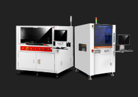
When combined with CNC-style programming and intuitive navigation, systems such as the I.C.T-7900 enable efficient sampling across different boards and products. This approach supports both routine quality checks and deeper engineering analysis, without the complexity and expense of over-specified inspection platforms.

Safety and compliance are not optional details—they directly affect operator protection, regulatory approval, and whether the system can run continuously without interruption. Ignoring these factors often leads to unexpected downtime or costly retrofits after installation.
Modern cabinet-style X-ray systems are designed with comprehensive shielding and interlock protection. In normal operation, radiation leakage is typically far below FDA and OSHA limits, often under 0.5 mR/hr measured at a distance of 5 cm from the enclosure.
Effective radiation safety follows the ALARA principle: minimizing exposure through proper control of time, distance, and shielding. When these principles are built into the system design and daily operating procedures, X-ray inspection remains safe for operators and compliant with regulatory standards.
Long-term reliability depends on proactive maintenance planning. Annual calibration, routine system checks, and periodic tube performance verification help maintain stable image quality and inspection accuracy.
Sealed tube systems generally offer predictable lifetimes and minimal maintenance requirements, which reduces unplanned downtime. To ensure consistent uptime, many factories also include service agreements and spare planning as part of their ownership strategy rather than treating maintenance as an afterthought.
Before committing to an X-ray system, walk through the following checklist to confirm alignment between inspection needs and system capability.
Start by identifying which boards and component types will be inspected most frequently. Define the specific defects that must be detected, such as voiding, head-in-pillow, bridging, or insufficient solder. Clarify your required daily or hourly throughput to avoid creating a new production bottleneck.
Decide whether inline or offline placement best fits your production flow. Evaluate which software functions are essential, including automatic void calculation, image analysis tools, and MES or SPC integration. Finally, confirm that the system meets all local radiation safety and compliance requirements to avoid installation delays or operational restrictions.
Successful X-ray selection starts with clearly defining your defect risks and production volume before choosing inspection technology. The right balance between 2D, 2.5D, and 3D CT depends on application needs—not on maximum specifications.
Balanced system design and strong software capabilities consistently deliver more value than extreme resolution alone. For many factories, offline X-ray inspection provides the most practical combination of flexibility, performance, and cost, while inline systems are justified only in true high-volume environments.
Above all, total cost of ownership should guide the decision. Avoid over-specifying features that add cost without solving real problems, and choose an X-ray system that delivers reliable inspection results economically and consistently over its entire service life.
No, for most basic BGA void checking and process monitoring, 2D or 2.5D systems suffice and cost far less. 3D CT becomes essential only when you need precise Z-axis location of voids (e.g., interface vs center), layer separation on double-sided boards, or compliance with strict automotive/medical standards requiring volumetric quantification. Start with background: Voids form from trapped flux gas during reflow; IPC-7095 allows up to 25-30% total voiding in balls depending on product class.
A good 2.5D system with tilt views reveals void size, position, and head-in-pillow risks reliably. Example: Consumer electronics factories routinely use 2.5D offline systems for 100% sampling with excellent yield control, saving 40-60% versus CT.
ROI depends on defect escape costs avoided. Steps include: Estimate current rework/field failure rate from hidden defects (e.g., 2-5% for BGA issues). Calculate average cost per failed board (rework $50-200, field return $500+). Multiply by annual volume to get potential savings. Subtract system TCO (purchase + 3-5 years maintenance/training). Divide savings by TCO for payback period. High-volume lines (>50k boards/year) often see <12-month payback from reduced rework.
Low-volume/NPI gains value through faster debugging and fewer customer complaints. Real example: A medium-volume factory reduced BGA rework by 80% after adding offline X-ray, paying for the machine in 18 months via labor savings alone.
Modern sealed-tube systems need minimal maintenance: annual calibration/certification for accuracy and safety compliance, periodic detector cleaning, and software updates. Open-tube models require filament replacement every 1-2 years. Budget for preventive service contracts (5-10% of purchase price annually).
Daily: simple warm-up and stability checks. Radiation safety surveys yearly. Uptime typically exceeds 98% with proper care. Compared to AOI, X-ray maintenance costs less since no moving optics get contaminated.
Rarely for volumes under 20-30k boards/month. Inline adds complexity, space, and cost while risking line bottlenecks if cycle time exceeds takt. Most medium-volume factories use offline systems for 5-20% sampling plus post-reflow AOI/SPI, achieving equivalent quality at lower investment. Inline pays off only when 100% hidden-joint inspection is mandatory (e.g., aerospace) or rework costs are extremely high.
Example: Many automotive suppliers run medium volume successfully with offline 2.5D X-ray stationed near the line for rapid feedback.
Critically important—often more than raw hardware specs. Good software provides automatic void measurement (repeatable per IPC), defect classification libraries (reduces operator skill dependency), and MES/SPC export for trending. Poor software leads to slow manual analysis and inconsistent results. Modern systems use AI-assisted judgment, cutting review time 50-70%. When evaluating machines, test software usability with your actual boards—it's the difference between a tool that sits unused and one that drives daily yield improvement.