English
Views: 0 Author: Site Editor Publish Time: 2025-08-05 Origin: Site


Did you know that even minor defects in Surface Mount Technology (SMT) assemblies can lead to costly delays and rework? SMT plays a vital role in modern electronics, driving compact and high-performance designs. However, defects in the assembly process can severely impact product quality and manufacturing efficiency. In this article, we’ll explore the importance of preventing defects in SMT, focusing on how clean, defect-free assemblies lead to more efficient production. You’ll learn about common issues and how to tackle them for smoother operations and better results.
")
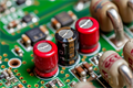
SMT assembliescan face several issues during the manufacturing process. Here are some of the most common defects:
Tombstoning: This occurs when a component stands upright, resembling a tombstone, due to uneven soldering. It's often caused by inconsistent heat distribution during reflow.
Solder Bridges: Excess solder can create unintended connections between adjacent pads or leads. These can cause short circuits or malfunctioning parts.
Component Misalignment: When components are not placed correctly on the PCB, it can lead to poor connections, affecting the functionality of the circuit.
Insufficient Solder: Not enough solder paste applied can result in weak or broken joints. This can compromise the connection and lead to device failure.
Cold Solder Joints: These appear dull or cracked instead of smooth and shiny. Cold joints are weak and prone to breaking under stress or vibration.
Other Common Issues: Missing components, solder balls, or even dirt on the PCB can also lead to performance problems.
Defects can severely impact the quality and performance of the final product. Here’s how:
Impact on Functionality: If defects like tombstoning or solder bridges occur, components may not work as expected, causing malfunctioning devices.
Impact on Reliability: Over time, defects such as cold solder joints or misalignment can lead to failures during operation, reducing the product's lifespan.
Economic Impact: These defects often require costly rework or replacement. They also result in delays, impacting production schedules and overall manufacturing efficiency.
Proper PCB design is crucial for preventing defects in SMT assemblies. Here's how you can optimize the design:
Design for Manufacturing (DFM) Guidelines
Adhering to DFM guidelines ensures the PCB is optimized for assembly. Focus on the right pad sizes, spacing, and thermal management. Properly designed pads and spacing reduce issues like tombstoning, which occurs due to uneven heating. By managing thermal flow effectively, you can minimize defects and ensure uniform heat distribution during reflow.
Optimal Component Placement
The way components are placed impacts the performance and reliability of the assembly. Placing components logically reduces signal path lengths and helps avoid errors. Group related components together. This minimizes the need for vias and improves electrical performance. This method not only reduces complexity but also improves the overall functionality of the PCB.
Footprints and Alignment
Ensure that footprints are correctly matched with component leads. Proper alignment of pads and component leads is key to preventing misalignment during assembly. Misalignment can lead to poor solder joints, which can affect the device's performance. Consistency in footprint design ensures smooth, efficient soldering and reduces defects like cold joints.
Selecting High-Quality Solder Paste
Importance of viscosity, paste properties, and consistency.
How high-quality paste reduces solder defects such as bridging or insufficient solder.
Choosing the Right Components
How high-quality components reduce the risk of defects.
Ensuring compatibility between components and the assembly process.
Using Reliable PCB Materials
Ensuring the quality of the PCB itself to avoid assembly issues like poor solder wetting.
Calibration of Pick-and-Place Machines
Importance of regular calibration to ensure accurate component placement.
How well-calibrated machines reduce misplacement and the risk of defects.
Stencil Printer Calibration
Ensuring consistent solder paste deposition through proper stencil maintenance.
The role of regular stencil cleaning to avoid clogging and ensure uniform paste release.
Reflow Oven Calibration
Maintaining proper temperature profiles to prevent thermal defects such as cold solder joints and tombstoning.
Regular reflow oven maintenance to ensure accurate temperature control during the process.
Implementing Statistical Process Control (SPC)
Using SPC to monitor critical parameters like solder paste volume and reflow temperatures.
Setting control limits for parameters to detect deviations early and maintain consistency.
Reflow Profiles
How to optimize reflow profiles to avoid defects like tombstoning and insufficient solder.
Ensuring the correct ramp-up and peak temperatures to achieve uniform solder wetting.
Stencil Cleaning and Alignment
Regularly cleaning stencils to prevent paste build-up and misalignment, which can cause defects in soldering.
Proper Handling Techniques
Educating personnel on minimizing contamination and damage during assembly.
How training helps reduce human error and improve process consistency.
Training on Defect Identification
Importance of detecting issues early through visual inspection and automated tools like AOI and X-ray.
Training employees to identify defects such as tombstoning, cold solder joints, and misalignment.
Documenting and Standardizing Processes
Developing clear, comprehensive documentation to ensure consistency across shifts and teams.
The role of documentation in establishing process standards to minimize defects.
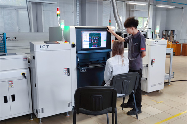
Automated Optical Inspection (AOI)
How AOI helps detect defects early in the process, especially issues like misalignment and solder bridges.
The importance of post-reflow AOI inspection to identify defects that could affect assembly.
X-ray Inspection
The role of X-ray inspection for hidden defects, particularly in BGAs and other complex packages.
How X-ray inspection allows detection of solder issues that are invisible to the naked eye.
Manual Inspection
When manual inspection is necessary and how to carry it out efficiently to ensure proper component placement and solder joint formation.
Rework Procedures
Techniques for reworking defects like tombstoning, solder bridges, and misaligned components.
Using hot air rework stations and desoldering tools to fix misplacements or excess solder.

To ensure clean and efficient SMT assemblies, following these best practices for PCB design is key:
Designing for Easy Assembly
Keep components on one side of the PCB to simplify the process. This reduces the risk of errors and makes the assembly less complex. A clear, organized layout helps avoid mistakes during soldering. It also ensures the assembly process is smooth and faster.
Avoiding Overcrowding
Make sure there's enough space between components. Proper spacing allows for better soldering and testing. When components are too close, it can be hard for machines and inspectors to check them. Overcrowding also affects solder joint quality, potentially leading to weak connections or failures.
Proper handling of components is crucial to maintaining high-quality SMT assemblies. Here are some best practices:
Minimizing Component Handling
Excessive handling can cause contamination or even damage to sensitive components. When components are touched too much, oils and dirt from your hands can affect soldering. Use appropriate equipment, like tweezers or vacuum tools, to minimize handling and reduce the risk of damage.
Storing Components Properly
Store components under controlled conditions to prevent degradation before they’re used. Keep them in environments with controlled temperature and humidity. Improper storage can lead to oxidation or moisture absorption, which can compromise the components' performance during assembly.
Advanced technologies play a vital role in preventing defects during SMT assembly:
Using Advanced Inspection Tools
Automated Optical Inspection (AOI) and X-ray systems significantly improve defect detection rates. These tools allow for high-precision inspection, reducing human error and ensuring consistency. In high-volume production, they help maintain high-quality standards by catching defects early in the process.
Leveraging Thermal Imaging
Thermal imaging can be used to detect uneven heating during reflow. This helps optimize reflow profiles and ensures uniform heat distribution. Identifying areas of concern with thermal imaging can prevent thermal defects, ensuring soldering quality and enhancing overall assembly efficiency.
Identifying the Cause of Tombstoning
Tombstoning happens when a component stands upright, usually due to uneven soldering. To prevent this, check and adjust your reflow profiles to ensure even heating. It’s crucial that the solder paste melts uniformly on both sides of the component.
How to Fix Tombstoning
If tombstoning occurs, reflow the component again. Adjust the solder paste volume to ensure an even amount on both pads, helping the component settle properly. Also, review your reflow profile to ensure the heat is distributed evenly.
Identification of Solder Bridges
Solder bridges occur when excess solder creates unintended connections. You can spot these bridges using visual inspection or Automated Optical Inspection (AOI) systems. Look for shiny, unwanted solder between adjacent pads or leads.
How to Correct Solder Bridges
To fix a solder bridge, use solder wick or desoldering braid. Place the braid on the bridge and apply heat using a soldering iron. The solder will be absorbed into the braid, leaving the pads clean.
Detecting Misalignment
Misalignment occurs when components are placed incorrectly. You can detect misalignment using automated tools like AOI or manual checks. Pay attention to the accuracy of component placement to avoid future connectivity problems.
Reworking Misaligned Components
If you notice misalignment, rework the component using a hot air rework station. If necessary, remove the component entirely, clean the pads, and replace it with fresh solder paste. Reflow the component to secure it in place.
Identifying Insufficient Solder
Insufficient solder results in weak joints or gaps in solder connections. Visual inspection or X-ray inspection can help spot these issues. Look for incomplete joints or visible gaps that signal a lack of solder.
Fixing Insufficient Solder
Add solder using a fine-tip soldering iron. Apply flux to ensure good adhesion. Be careful not to add too much solder, as this could create new issues like bridges.
Identifying Cold Solder Joints
Cold solder joints are dull, cracked, and unreliable. These joints usually form when the solder doesn’t reach the proper temperature during reflow. Look for joints that appear matte or inconsistent in texture.
Reworking Cold Joints
Reflow cold solder joints using a soldering iron or hot air tool. Apply heat until the solder becomes shiny and smooth. Adding flux can help the solder flow evenly and create a reliable joint.

To prevent SMT defects, focus on best practices in design, handling, and inspection. Regular calibration, proper placement, and thorough inspections help ensure clean assemblies. A continuous improvement mindset is key to maintaining high-quality standards. Regular monitoring and training keep your process efficient. Proactively addressing potential issues leads to better productivity, fewer defects, and lower costs.
A: Common defects include tombstoning, solder bridges, component misalignment, insufficient solder, and cold solder joints.
A: Adjust reflow profiles to ensure even heating and ensure proper solder paste volume on both pads.
A: Automated Optical Inspection (AOI) and X-ray inspection are excellent tools for detecting defects in SMT assemblies.
A: Ensure accurate placement using automated tools like AOI and check manually for proper alignment.
A: Add solder using a fine-tip soldering iron and apply flux to ensure proper adhesion.
A: Reflow the cold solder joint using a soldering iron or hot air tool to ensure it becomes smooth and shiny.