English
Views: 0 Author: Site Editor Publish Time: 2025-08-01 Origin: Site


Have you ever wondered how manufacturers ensure the reliability of their PCBs? The answer lies in thorough failure analysis and aging tests. PCBA (Printed Circuit Board Assembly)is a cornerstone of modern electronics, driving product performance and longevity. But how can we be sure it's up to the task? In this post, we'll explore the importance of failure analysis and aging tests for ensuring the quality of PCBA. You'll learn how these tests improve reliability, reduce failures, and extend the lifespan of electronic products.

Failure analysis in PCBA is the process of investigating and identifying the cause of a failure in the assembly. It helps us understand why a PCB failed and how to fix it. This process is crucial in maintaining product quality and improving designs for better performance. In the world of electronics, failure analysis is key to ensuring reliability. Without it, you may face recurring issues in PCBs, leading to costly repairs or customer dissatisfaction. The primary goal of failure analysis is to pinpoint the exact cause of the problem. Once the failure is identified, it can be corrected to prevent future issues, improving both the design and manufacturing processes.
Poor design is a common cause of PCBA failure. When the design doesn't meet the required standards, issues like improper component placement, inadequate trace width, or insufficient thermal management can occur. These flaws may cause the board to malfunction, affecting the product's overall functionality. Common design flaws include:
Inadequate trace width for current handling.
Poor thermal management leading to overheating.
Insufficient clearance between components.
Manufacturing defects occur during the assembly process. These defects can include poor soldering, misaligned components, or contamination. These issues can compromise the integrity of the board, causing short circuits, intermittent connections, or complete failure. For example, improper soldering can result in weak joints, leading to unreliable connections. Similarly, misplacement of components can lead to operational failures.
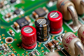
Components used in PCBAs may fail due to inherent defects or poor quality control. Subpar components, whether from a faulty batch or incorrect specifications, can cause performance issues, malfunctioning, or even complete failure of the PCBA. It’s crucial to verify the quality of components during the sourcing and inspection process. Faulty capacitors, resistors, or ICs are common contributors to PCBA failure.
Environmental factors like temperature, humidity, and vibration can significantly impact PCBA performance. For instance, temperature extremes can cause thermal stress, leading to cracks in the PCB material or solder joints. Similarly, exposure to high humidity can lead to corrosion, affecting the board's functionality. Vibration, especially in high-stress applications, can cause mechanical damage, affecting components and solder joints. Understanding and simulating these environmental conditions during testing helps ensure that PCBs can withstand real-world conditions.

Before diving into a detailed analysis, you must first confirm the failure. This ensures you’re solving the right problem. To verify a failure, start by documenting all observed symptoms. Collect data on the failure’s occurrence, whether it’s a complete failure or intermittent. Record the board’s conditions and any error codes if applicable. This helps set a clear foundation for further testing.
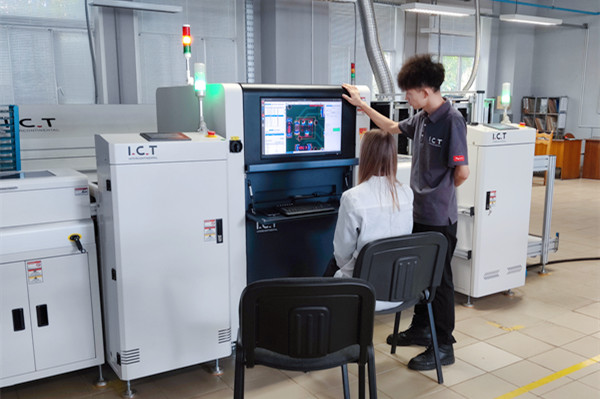
Non-destructive testing (NDT) involves techniques that assess the PCBA without causing damage. Common NDT tools include:
X-ray: Used to view internal components and solder joints.
Infrared Thermography: Detects heat patterns and identifies overheating issues.
Acoustic Microscopy: Helps spot hidden delaminations or internal damage. These techniques are essential because they prevent further damage to the PCBA while giving valuable insights into internal defects.
Once the failure is verified, you need to pinpoint its exact location. Fault isolation helps identify which part of the circuit is faulty. Methods for fault isolation include:
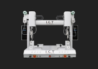
In-Circuit Testing (ICT): A quick way to check for continuity, shorts, or open circuits.
Flying Probe Testing: This is useful when the PCBA doesn’t have a test fixture, as it can probe various points on the board. Isolating the problem allows you to focus your analysis on the precise areas that need attention.
Sometimes, non-destructive methods aren’t enough, and destructive testing may be required. Destructive testing can involve:
Cross-sectioning: Cutting through the PCBA to inspect internal layers.
Decapsulation: Removing the package of integrated circuits to check for defects. These methods give you a closer look at the internal structure, which is helpful for severe or hidden failures that can’t be detected externally.
Root Cause Analysis (RCA) is the next step to determine the underlying cause of the failure. It’s not enough to fix the issue; you need to prevent it from happening again. Common RCA techniques include:
Fishbone Diagrams: Helps identify various factors contributing to the failure.
5 Whys: Asking "why" multiple times to dig deeper into the root cause.
Failure Mode Effects Analysis (FMEA): Systematically identifying potential failures and their impact. RCA will guide you in finding the true cause, not just the symptoms.
After identifying the root cause, it’s time to implement corrective actions. This could involve design changes, manufacturing process adjustments, or material improvements. For example:
Improving the soldering process to avoid cold solder joints.
Changing the component placement to reduce thermal stress. The key is to ensure the failure doesn’t happen again. Corrective actions must be followed by retesting to verify the fix.
Aging tests simulate real-world environmental conditions that a PCBA may face during its lifecycle. These tests help determine how long the PCBA can function without failure. By accelerating certain factors like temperature or humidity, aging tests identify hidden issues before they cause significant damage.
These tests are necessary because they highlight weaknesses in the design or materials that might not show up during regular operation. By running these tests, manufacturers can identify potential failures and fix them before the product hits the market.
Burn-in testing involves running the PCBA under elevated temperature conditions for an extended period. The goal is to trigger early failures that might occur in the initial stages of the product’s life. Typical conditions include:
High temperatures, often above the operating range.
Extended testing periods (24 hours or more). This process helps detect issues like faulty components that would otherwise go unnoticed.
Temperature cycling tests how well the PCBA can handle rapid temperature changes. By exposing the board to alternating hot and cold conditions, manufacturers can assess its thermal resilience. Effects include:
Thermal stress on materials, which can lead to cracking.
Expansion and contraction of components, leading to solder joint failure. These cycles simulate environmental shifts, helping to ensure the PCBA won’t fail under typical operating conditions.
PCBA boards are often exposed to moisture in real-world environments. Humidity testing evaluates how well the PCBA resists the damaging effects of moisture.
Testing involves:
Exposing the PCBA to high-humidity environments for extended periods.
Observing potential corrosion and material degradation. It’s important because moisture can lead to short circuits or other failures.
Vibration testing simulates mechanical vibrations, such as those caused by transportation or machinery. It helps assess the PCBA’s durability and its ability to stay intact during real-world conditions. This test ensures the PCBA will continue to work reliably in moving or vibrating environments.
Selecting the right aging test depends on the PCBA’s intended use. Each board faces different environmental conditions, so the test should simulate these factors. For example, if the PCBA will be used in high-temperature environments, you might choose a burn-in test. For products used outdoors, you might prioritize humidity testing. Ask yourself:
Where will the PCBA be used?
What environmental stressors will it encounter?
Once you’ve chosen the appropriate test, you need to set the right parameters. This includes determining the conditions the PCBA will be exposed to during testing. Key parameters include:
Temperature: How hot or cold will the board be during operation?
Humidity: What level of moisture exposure does it need to withstand?
Vibration: Is there any mechanical movement to simulate? The duration of the test is also important. Most tests last anywhere from a few hours to several days. The longer the test, the more it can simulate real-life stress.
During aging tests, it’s crucial to track progress and gather data continuously. This helps identify any issues early on. You should monitor:
Environmental conditions: Are temperature and humidity within the desired range?
Component performance: Does any part start showing signs of failure? Keeping track of these metrics ensures you can make adjustments if needed and also helps in interpreting test results.
After completing the aging tests, it’s time for evaluation. You’ll analyze the results to determine how well the PCBA holds up under stress. This includes inspecting for any failures or signs of wear that could affect performance. Consider:
Were there any unexpected failures?
Does the PCBA still meet its operational requirements after the test? This final evaluation helps predict the long-term reliability of the PCBA in its intended environment.
Inspecting the components is essential to ensure they meet quality standards. Look for signs of damage, such as cracks, discoloration, or burnt areas. Each component should also match its specified values and tolerances. Subpar components often cause reliability issues, so thorough checks are needed. Focus areas include:
Physical damage (e.g., chips, cracks).
Correct part numbers and values.
Signs of overheating or degradation.
Solder joints are critical in ensuring proper connections. Poor soldering can lead to intermittent failures or complete loss of function. Using magnification, inspect the joints to make sure they are solid and well-formed. Common issues include cold solder joints, bridges, or weak connections. Key inspection points:
Solder joint integrity (smooth and shiny).
No solder bridges or cold joints.
Proper component orientation.
Checking the circuit’s continuity ensures that all traces and connections are intact. A multimeter is commonly used for this task. If there is a break or fault, the circuit won’t function correctly, so verifying this step is crucial. Test for:
Unbroken traces and vias.
No shorts between traces.
Functional connections between components.
Functional testing checks if the PCBA works as intended, even under stress. This can include powering the board on and testing its features, such as output signals or interactions with other devices. Stress testing might involve running it at higher temperatures or over prolonged periods to ensure it doesn’t fail in real-world scenarios. Key tests include:
Powering the board and verifying outputs.
Stress testing under high temperatures or load conditions.
Ensuring it meets design specifications during operation.
PCBA boards often face extreme conditions like heat, humidity, and vibration in their real-life applications. Exposing the board to these conditions helps ensure it can withstand the environment in which it will be used. Common tests involve:
High and low-temperature testing (thermal cycling).
Humidity exposure to check for moisture resistance.
Vibration testing to assess durability under movement.
Visual inspection is one of the simplest and most effective ways to identify issues with a PCBA. By using magnification tools like microscopes, inspectors can examine solder joints, component placement, and surface conditions. What you can spot:
Solder joint issues like cracks or cold solder.
Component misplacement or damage.
Surface contamination such as dust or flux residue. This technique is especially useful in identifying problems that may not be visible to the naked eye.
Non-destructive testing (NDT) allows us to examine the internal structure of the PCBA without damaging it. This is crucial for high-value or delicate assemblies. Tools like X-rays, infrared thermography, and acoustic microscopy can provide deep insights into hidden defects. Key tools and their benefits:
X-rays: Reveal internal solder joints, vias, and hidden component defects.
Infrared thermography: Detects heat distribution and identifies areas of overheating.
Acoustic microscopy: Finds internal delaminations or cracks without disassembling the board. These methods help us identify flaws that could lead to future failures but don’t harm the board in the process.
Electrical testing tools ensure that all circuits are functioning as expected. These tools are essential for verifying electrical integrity and ensuring the board operates correctly under stress. Common techniques include:
In-Circuit Testing (ICT): Checks for shorts, opens, and correct component placement.
Flying Probe Testing: Ideal for prototypes, it tests various points on the board without requiring custom fixtures.
Boundary Scan Testing: Tests internal connections using a set of scan chains, especially for boards with complex, multi-layered designs. These tests help ensure the board functions properly before moving to the next stages of production.
Material testing tools are used to assess the properties of the PCBA's materials. By analyzing the PCB’s substrate and components, we can determine whether the materials meet required standards. Tools include:
Scanning Electron Microscope (SEM): Analyzes surface details and material structure at high magnification.
Energy-Dispersive X-ray Spectroscopy (EDS): Identifies elements and material composition.
Fourier-Transform Infrared Spectroscopy (FTIR): Assesses material composition, including organic and inorganic materials. These tools provide essential data on the quality of the materials used in PCBAs, ensuring they are suitable for the intended application.

To conduct thorough failure analysis and aging tests, focus on verifying failures, isolating faults, and using appropriate testing tools. Consistent testing ensures long-term reliability and highlights potential weaknesses. Continuous testing is crucial to maintaining the performance and lifespan of PCBAs. Implementing lessons from these tests into the design and manufacturing process can significantly improve PCBA longevity and prevent future failures.
A: Failure analysis identifies the root cause of PCBA issues, while aging tests simulate long-term environmental stress to predict PCBA longevity.
A: Aging tests help identify hidden weaknesses and ensure the PCBA can withstand real-world conditions, extending its lifespan.
A: Destructive testing is used when non-destructive methods can't reveal internal issues, such as internal delamination or material defects.
A: Common issues include poor soldering, component misplacement, design flaws, and environmental damage.
A: It helps identify weaknesses in design or process, allowing for improvements to enhance reliability and reduce defects.
A: Key factors include temperature, humidity, vibration, and thermal stress, which affect the PCBA’s performance.